|
|
Post by Lucass2T on Apr 18, 2024 3:15:58 GMT -5
Sorry to see the wheel got damaged. Maybe you can smooth the rough edges, have some paint made in the same color and do some touching up.
More important is to figure out why the arm is touching the wheel and what and where there is so much flex. It should be a super rigid setup this way.
Good luck buddy and try not to let a stupid scooter get to you this way.
|
|
|
|
Post by 90GTVert on Apr 18, 2024 4:33:19 GMT -5
More important is to figure out why the arm is touching the wheel and what and where there is so much flex. It should be a super rigid setup this way. I don't think this is really abnormal. Ryan commented about spacer washers on his so it would bottom out on the adapter before it could hit the wheel. Then I took another look at a couple of vids of people using the Polini torsen and the nut section and washers act as a stop on that too. I think it's just an oversight in the design of the adapter on my part. I figured just keep the nut section against the hub to provide a strong base. The companies that make them largely seem to put the hex section out farther and use that as a stop, again in combination with spacers. I think I should have at least made a shoulder as a stop, but that would have been a lot easier if I had a thinner compensator ring... which I had no idea where to get when I made it. Plus, at the time I really didn't know where the bearing would be riding so I made something with a lot of wiggle room. Anyway, I'm gonna try to make a snug fitting spacer to salvage the adapter and I think that should do it. As far as the wheel goes, I'm not getting it coated. It's fine. Battle scars from hopefully a lesson learned. I haven't been thrilled with the color since I got them done anyway (wrong color from the coater) and they seem to be fading... which the other neon wheels didn't do with the right color on them. If I get spare cash someday then I may try to get someone different to make them bright neon like they were supposed to be, but right now I'd rather use what funds I have to see if I can get it running better and quicker. I'm much more concerned about the carb. That one I'm lost on. My next thought is to try to mimic the Malossi curves on the programmable ignition. Maybe eliminate a possibility there. I don't see how that makes it deliver more fuel though, because that plug and piston crown look like there's either a real shortage of fuel or so much that everything is washed... but the breakdown, EGT and feel say it's a lack of fuel. My fuel system is a 2.5 gallon tank with 1/4" hoses, shutoff and filter so it couldn't get much simpler that way. It would seem like it has to be in the carb... plus the 28mm ran fine when swapped back on as a sanity check some time ago. I still come back to timing because I've seen first hand that I could run the thing without a main jet at all or gigantic jets and it would get hot and then I moved the timing 3 degrees and suddenly the jetting requirements were different. It may be much more picky than I'd think... even though I really don't understand why it would make such a huge change. But then even after getting things to improve, it started to get hot on WOT passes after the CVT was better dialed in and then took out the piston after I ran it up to 70 and that could be pointing to fuel supply. The easy fix is to go back to the 28mm... but I have already seen better 0-60s and think it could get better still if I could ever get this thing right. I'm not sure I'm capable of tuning a flat slide though. The Lectron sure didn't like me and now the PWK... but neither are from a lack of effort. Oh, I looked at clear bowls and ordered one on amazon that I hope fits. I was really tired so I may have missed something, but it'll be here Friday. Would be nice to at least see if fuel level drops, though I'm kinda scared to run it WOT with the shortage of pistons. |
|
|
|
Post by 90GTVert on Apr 18, 2024 6:42:44 GMT -5
I may be way off of where I need to be with timing in the powerband. My calculated timing based on mm BTDC settings is way off of what I'm observing. You should see "Calc" and "Obs" to make it clear which I've actually checked and which are calculated. Some numbers are missing because I figured I really just need a few spots since the curve should move forward or backward and not change otherwise. Seems like I'm wrong there too though.  It seemed to like somewhere around 15-16 degrees of advance at peak around 13,500RPM. Now it's probably 10-11 degrees. It was around 12 or so when I was struggling with gigantic jets using the MVT and advancing 3 degrees to about 15 put me in normal jetting range. I definitely want to check mm BTDC now, to see if it could have changed with removing and reinstalling the flywheel. It's drastic though. What I calculated and observed are roughly 10 degrees different at some points, less at others. I might have to put the degree wheel back on as well to double check because now I'm wondering if somehow I could have made an error in timing indicator setup. Can't explain why it would be so far off aside from that or the rotor moving. |
|
|
|
Post by 90GTVert on Apr 18, 2024 16:24:11 GMT -5
I hope I’ve got the easier of the issues covered. I made 2 aluminum spacers. Decided that nothing really had to be press fit. Just snug seems like it should be fine. I had to do 2 pieces because there’s no way I can get the compensator ring on with a spacer in part of its area. I tried. It leaves a little room for the arm to move, but it would leave 2mm of space between the wheel and arm if the arm is pushed right up against it. Aluminum is easier to make and I’m hoping that if anything wears it would be these parts instead of the much tougher to make adapter.    |
|
|
|
Post by 90GTVert on Apr 20, 2024 20:02:40 GMT -5
I don't know what's up with the timing. I checked again and it looks like it's about 15 degrees retarded from the original setting... but I moved the stator 8 degrees and change. Even weirder is the fact that I couldn't get the timing mark to align at TDC with the indicator so I painted a second line on with a degree wheel at 0. Checked timing with that and it was way off. Not sure how that happens. I even double checked and 0 10 20 30 and 40 matched on the degree wheel and indicator... yet when I checked timing that way it was over 50 degrees BTDC on the indicator and 1.85mm BTDC (where the timing appears to be set just like before the flywheel came off and back on) is ~21.5* on the degree wheel as it would be calculated. I've setup degree wheels too many times and I was baffled by how it could be way off marking the flywheel via a degree wheel's 0 vs setting TDC on the indicator directly with a piston stop. (Second time for the 15 degree reading mentioned was done with the original mark and a piston stop.) Anyway, what I can tell you for sure is that no way that I check timing is it where I think it should be in the powerband. Maybe if I check it a few more times? lol Also for sure... the timing light doesn't like being on for that long. I assume high RPM doesn't help at all. Started to melt the plastic. Works just fine.  I think my plan is to see if I can setup the ignition to have the same curve as MHR uses. Well, the average of the MHR curves for the 94cc. The instructions for the timing curve program basically say that 0 on a timing graph is actually your mechanical timing setting... wherever the flywheel is. So if I set the flywheel to 30*, every timing point is above 30*. Not sure why it would work this way with programmed curves, yet you can set it to 30* with the original CDI curves and it goes below 30*. Whatever the case may be, I made the curve to be used with the rotor set at 10* BTDC or 0.42mm BTDC, which will require the removal of the woodruff key. That's pretty similar to the MVT's timing, which started easy... though some of the starting is just the fact that the PVL ignition won't make a spark till RPM is a little higher. The green mechanical timing line that I stuck in is sort of confusing I guess, since mechanical timing is again 0* on the chart as I understand it. I put it there just as a note of where to set the rotor. I will absolutely need to verify this timing though, surely multiple times.  I made a curve based on Wobbly's timing remarks that John posted earlier in the thread as well, but that will be for another time. # concern right now is trying to get the setup working and keep a piston intact.  Speaking of the piston, I looked in the exhaust port to admire my 6.1 mile, nicely scuffed piston.  The clear bowl came in yesterday and it fits, but it took a little work because of the giant bellmouth that I use.   If nothing else, it's pretty photogenic. You can see that I just stuck a vacuum cap on the unused barb.  I tested fuel flow as well. Replaced all hoses just because I wasn't sure if they all matched size. Fuel flow was the same before and after, at about 500ml in 30 seconds which is a nice round liter per minute. That was all 3/16" or 5mm hose, because the 1/4" doesn't fit the barb on the carb well. The bowl filled very quickly. Now I just hope the plastic bowl sitting on the fender doesn't rub through quickly and soak my back tire in gas and oil. I rotated the filter around so it hit the fender as much as possible, but there's still contact. Mostly I just need it long enough to see if fuel level is getting low, so hopefully it and my piston can make it through some tests once I get the ignition setup. |
|
|
|
Post by 90GTVert on Apr 23, 2024 6:57:04 GMT -5
The documentation with the S6/PVL/Andromeda is such a joy to work with.
I removed the woodruff key and lapped the flywheel and crank together, which took quite a while to get it to look mostly uniform. Set the rotor at 0.42mm BTDC, which should be 10 degrees mechanical timing to pair with the curve with 25* at low revs to make 35*.
Checked with a timing light and it was idling at a few degrees BTDC. Definitely accurate, because when I revved it up a little it started to popping like it was coming onto a 2-step.
So, the pdf with the software says that mechanical timing plus advance equals actual advance. The zero degree line in the graph is supposed to represent mechanical timing. So if I set the mechanical timing at 10 degrees, the graph actually starts at 10 degrees because 0=10... or think of it as 10 degrees needs to be added to everything. I want 35 degrees from that, then I need to add 25 degrees. Simple enough, right? They even give you multiple examples to make sure you get it.
It looked like I needed 30 degrees or more of advance added to my 10+25 setting.
In reality, it seems that it is anticipating the 0* line to be at actual 0* when the mechanical timing is set at about 30* as it is with the marks aligned at 3.59mm BTDC. It would appear to be easier to use that way, if users could just set the curve in the software where they actually want it and leave it alone from the initial setting. Unfortunately, no one bothered to tell anyone in the documentation for the software or the ignition that this was how it worked. Instead they go over the wrong instructions with you over and over, never telling you that you should leave it set as it is initially for custom curves and forget the addition.
I have a feeling I'm not the first or last one to waste their time setting everything up again only to find it incorrect. Worse yet, imagine you assume the timing is correct because it seems like a clear process as instructed and then you're on the 2-step when you rev and don't know why or maybe it's not so drastic and your performance is just way off. Way to go Stage6/PVL/Andromeda. Ultimately, S6 should have updated their booklet... just like they should have done to tell you that it bolts to an C/RC-One with no adapter needed. They want the cash for the fancy new ignition, but can't be bothered to reprint manuals with a couple of extra pics for the RC1 and notes about the programmable timing setup.
I set timing back to 3.59mm and adjusted the MHR clone curve to the actual figures, with 35 degrees of advance at low revs. I checked that and it's still wrong, but closer. It looks like it starts at 31-32* at 2000RPM and makes it's way to 29 degrees by 4000RPM, where it stays till 7000+ as it's supposed to, before retarding. Then it mostly follows the curve, but seems to get an extra degree off at higher RPM. Again this is a DIY indicator, so I may have a line a little off or maybe it's something to do with lag from the light at high revs. Usually I'm testing curves where I don't know what they're supposed to be or I'm checking things that I've tested before.
I'm figuring I should ignore the idle figures being high, and use the flat line section that does stay flat for the majority of the time that it should as the basis for adjustment. That means I need 6 degrees more advance. The easy way to get there should be to move the curve up 6*, but I don't even think it will take that much based on it's EIT (earliest ignition timing point) and even if it would, I'd prefer to get it setup in a way that I can expect programmed curves to at least closely match observed timing.
I can't say that I get why it's 6* off though. I use my camera as straight on as possible without some major setup process and zoomed in tight for setup of the ignition and timing indicator so I can be as accurate as I know how to be by reducing viewing angle errors. Plus, if I set the timing indicator (like a degree wheel) using the camera and then don't move the camera before testing with a timing light, then the camera is essentially zeroed with the indicator setup. My guess is the mm BTDC mark alignment is the issue, or it's something else they aren't telling you about in the ignition system. The mark alignment can be off by quite a bit with only the slightest movement, amplified by having the rotor stick out more than the stator mark.
TLDR : I'm having a lot of fun. 🤣
|
|
|
|
Post by 90GTVert on Apr 23, 2024 12:53:43 GMT -5
Just spent more than 30 minutes looking for the spacer sitting on the water pump hose after dropping it while removing the timing indicator. Swept the floor, moved stuff… there it was an inch away the whole time.  I’m gonna start painting small parts like candy canes so at least I can pretend I’m playing Where’s Waldo. |
|
|
|
Post by 90GTVert on Apr 24, 2024 1:13:59 GMT -5
After the timing was switched to 5.1mm BTDC, I printed a degree wheel with single degree graduations and taped it to my indicator to improve accuracy. I checked a couple of spots with an adjustable piston stop to verify that it was correct. The pics show how I use the camera to get a precise setting.    This is what I came up with. It's 1 degree too advanced down low, but matches up well on the higher RPM numbers. My curve should match all the way across, so I'm guessing this is a function of the light and delay for lack of a better explanation. It may be that it should be retarded 1 degree across the board, but I'm gonna call this close enough for a test ride. I wanna see if the bowl drains and I hope 1 degree won't make or break me.  I suppose I could make a custom "curve" that's flat and see if that drops a degree or so at higher RPM too. I guess another possibility is that the ignition system has more delay at higher RPM. A test wouldn't really tell me if it was the light or the ignition so I don't know that I'd learn anything useful. I already know it matches setting at high RPM so it wouldn't answer the question of if I should alter the curve or not because changing the whole curve 1 degree with the assumption that the light is retarding with revs would make it wrong if the ignition was actually the cause and moving timing only at low RPM to match what I aimed for if it was the ignition would leave it a degree too far advanced at high RPM if it's the light. It's just like the advance I see at 2000-3000RPM. I assume it's the ignition there on a flat section of the curve, but I don't know. Then you'd have to wonder if the whole thing is 2.5 degrees advanced if it's not. I'm aware that everything seems to be more difficult for me, but think about how accurate I attempt to be and how much stuff I check and then think about the average Joe that sets mm BTDC by eye and calls it a day. Most people make out just fine that way, so the idea of stressing over 1 degree of uncertainty is painted in a different light with that in mind. |
|
|
|
Post by 90GTVert on Apr 24, 2024 11:56:15 GMT -5
I got cameras setup on the torsen and carb and went for a test run. I did some dragy passes a couple of miles from home and realized that the carb cam was gone. The mount broke. That sucks, but I finished my runs before heading back. It averaged 1130 EGT at 60. Best results are typically low to mid 1200s. 10.06 average in the 1/8. RPM avg from 30-60MPH was 13150 to 13278, so it’s not getting quite enough RPM but it’s close. I think a smaller jet would help, but I’m gonna leave the 200 for another attempt at a bowl view. I headed home at about 20MPH but didn’t see the GoPro. Got the car and enlisted my mother to drive 1-3MPH so I could hang my head out of the window and look. It took some time, but found it roughly 2 miles from home. A little beat up, but still recording. I hadn’t done any WOT before it tried to escape so I still have to try again.     |
|
|
|
Post by 90GTVert on Apr 24, 2024 14:04:19 GMT -5
I’m not seeing coolant temp or it’s weird. It was negative 10 at one point. Trail Tech have lost their damn minds on shipping!!!  Thankfully, though it appears everyone must sell at their price, other retailers (eBay) will ship it for $5. |
|
|
|
Post by aeroxbud on Apr 24, 2024 14:46:45 GMT -5
That shipping is crazy for something that will fit in a padded envelope.
Lucky to get the camera back. 👍
|
|
|
|
Post by 90GTVert on Apr 24, 2024 17:45:25 GMT -5
@&$#!!!  It made one 1/8 mile pass fine. Next pass; it died in the upper 60MPH range with EGT at 1188. I looked at the bowl camera and the bowl is pretty much full. I’m lost. My last thought for the carb was the needle. Thinking maybe the fat tip on the HKJ is too much, but if it wasn’t allowing enough fuel then I wouldn’t think the EGT should still be low. Other thought is maybe the piston is too tight or the cylinder is shot now. Not sure where to go here. The C piston was in there for 800 miles so the BB shouldn’t be a problem. I’m back to questioning life as a whole. 🤦♂️ The car show is getting close and, even worse, the small bore rally in TN is basically a month away. I’m going broke and don’t have a running scoot or a clue how to fix it. Best guess for now is go back to the 28mm Dell and see if it still dies… if I have a working engine when I check it out. |
|
|
|
Post by 90GTVert on Apr 26, 2024 16:49:25 GMT -5
It didn't wanna start. Checked that before pulling it apart. The ring did feel a little stubborn, so I think that is likely the reason... paired with an ignition that won't make a spark in less than perfect conditions.             The aluminum on the non-thrust sides... the pin axis... can be felt by finger. Not fingernail... finger. It seems odd to me that the worst is there. Normally is the thrust axis. That didn't seem to take a lot more damage. Not saying anymore is good, but it's not like the pin axis. I'm not sure if maybe the wear on the thrust axis from last time causes it to then dig into the opposite axis or if something else is going on. I don't think this top end is gonna go back on. It may clean up OK, but how much can I put it through? Plus, it's not like it's easy to get another piston for closer to spec fit... at least not at a reasonable price or delivery time. Now it get's questionable for me... So I'm paranoid about the conrod/bearing/pin fit. I thought maybe it was a little too snug. Actually thought this during assembly when the pin was initially a little tough to push through and then I pulled it and reinstalled it and convinced myself that it wasn't too tight because it wasn't as difficult the 2nd time. I saved the 2 pistons that I've used before, along with their pins and bearings. They feel about the same in the rod. Wear doesn't look alarmingly different on any of them to me. If I use one of the old pistons without smeared aluminum on it, I can push the pin through the rod and bearing with ease. OK. Well, then I decide to check the small end of the conrod anyway. AFAIK it's supposed to be 17mm. The bearing is 13x17x17.7. I get 17.00mm if I measure up and down as it sits... which I would be exhaust to intake or I guess side to side. If I measure the opposite axis, which would be up and down in the bore, then I get 16.99mm. My measurements could be wrong. I tried with a snap gauge many times and used the calipers and micrometer both and measured with the calipers directly and all seem to tell me it's those numbers. Could be that I'm wrong and it's 17 and 17.01? Not even trying to get any closer than that. What I'm certain of is that the rod ID is smaller where it would be going up and down in the bore. I can take the snap gauge and set it in one direction and then it either gets loose or tight in the opposite, depending which way I'm trying it. No doubt there's a difference. A couple of things seem off to me here...Why would it either get smaller on the axis where I'd think it takes the most force, or get larger on the one that doesn't? I don't know a lot about cranks and rods, so is this common or at least something that others see? I'm hoping they made the side that should wear smaller and it's normal... but I have to expect that it should be round and that's purely wishful thinking out of despair. Is this crank certainly junk? I'm sure the rod could be replaced, but if I do it the crank may be junk anyway. Tried it once long ago and it went very bad. Right now the only thing that I know is that this sounds bad with a capital dollar sign. |
|
|
|
Post by 90GTVert on Apr 27, 2024 7:39:52 GMT -5
I've been talking to a guy that is trying to make his vertical Jog the quickest known. He's been messaging me for a while looking for info here and there. He's already very low 9s with low 5 second 0-60s on a 77cc. Looks like nothing you'd think twice about if it pulled up beside you too. In conversation he mentioned a weather tool being the same he uses for the pro-stock car, which caught my attention. Turns out he and his father have a machine shop and have been into racing his whole life. They even took a chunk of aluminum and turned it into a head for the pro-stock car. I know, this sounds irrelevant... but I figured I'd take the opportunity to ask him a question last night and told him about the conrod. He said he wouldn't think that 0.01mm would be an issue and that I'd probably worry about it though since I know now (true). The biggest concern he'd have would be if it were damaged the conrod could break. This doesn't look damaged at all. Again, on appearance it looks like it's new to me. I've been checking a few service manuals. Surprisingly, most don't say much at all about the conrod small end. The YZ125 manual for example just said to put the pin and bearing in and check for free play. Some literally say nothing. I did find this in a Vespa S 50 manual... 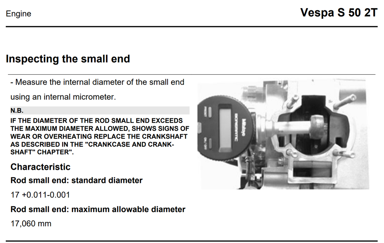 Looks like their conrod is supposed to be 16.999-17.011 standard. So that's already more deviation than I have, but they don't mention out of round. They do say maximum allowable is 17.060mm. They're allowing basically 0.05mm of wear or change and I'm at roughly 0.01mm. Again, I don't trust the snap gauge method beyond there for accuracy. Not even totally sure I'm accurate there, but it's about 0.01mm out of round. The manufacturers, from the manuals I've scanned... which is not a ton... don't say anything about out of round. |
|
sinfull
Scoot Enthusiast

Posts: 358
|
Post by sinfull on Apr 27, 2024 13:00:30 GMT -5
Wow, definitely putting up a fight. 😆
|
|


