|
|
Post by ryan_ott on Dec 1, 2018 19:28:44 GMT -5
I don’t think you could of asked for better results without a lathe. It looks damn good from my couch.
|
|
|
|
Post by 190mech on Dec 1, 2018 19:34:51 GMT -5
Great job!You know for sure the squish angle fits the piston dome now!!So glad to see you thinking "out of the box" to get a precise job done without machining tooling..  |
|
|
|
Post by oldgeek on Dec 1, 2018 20:08:37 GMT -5
Trust me, it is not "precision" As in I can see the piston wobble a bit as the head spins around it. Squish measurements may be all over the place! With that in mind I decided it would be a good idea to lap the actual working piston to the squish band a bit. Question what gets polished, or should I just leave it all as is? 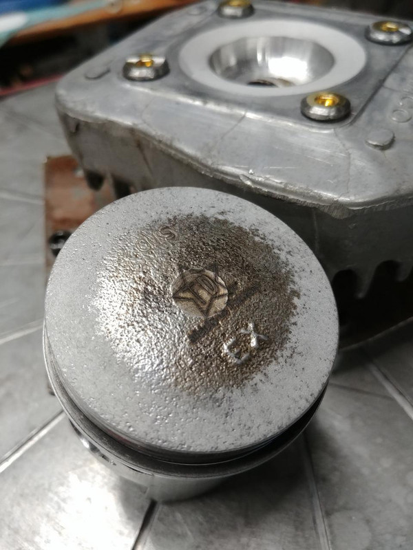 |
|
|
|
Post by oldgeek on Dec 1, 2018 21:09:05 GMT -5
I took the head off the fixture finally. Cleaned it up a bit and checked the CC's. I got exactly 9cc, a little short of the target of almost 10cc I was looking for. Ill go crunch some #'s and see what the corrected compression is now.
|
|
|
|
Post by gsx600racer on Dec 1, 2018 22:24:34 GMT -5
In the past, iv cleaned up a few casted top pistons. I first stamp/mark/prick punch the underside of the piston to mark the exhaust side. Then I knock down the high stuff with a dremel w/sand disc. Then "lightly" chuck in lathe(wrapped of course) and with sandpaper try to get rid of 80-90% of the pits then polish.
|
|
|
|
Post by SMALL CC TEK on Dec 1, 2018 22:39:49 GMT -5
That still looks good , with hand tools what more can you ask for ! I could not have done a better job no way in the world with hand tools good job
|
|
|
|
Post by oldgeek on Dec 1, 2018 23:55:56 GMT -5
I took the head off the fixture finally. Cleaned it up a bit and checked the CC's. I got exactly 9cc, a little short of the target of almost 10cc I was looking for. Ill go crunch some #'s and see what the corrected compression is now. If my calculations are correct I now have UCR = 14.49:1 and CCR = 8.16:1 using the 9cc head. I originally cut the combustion chamber with a burr I had on hand at the time. The burr has a less rounded profile at the tip than we wanted, but I used it anyway. It came out looking pretty good nonetheless. A couple burrs came in the mail this week, one from 190Mech (THANKS) and one I ordered myself. They are basicly identical and I just chucked one up in my router. The burr on top is the one I actually used to cut the combustion chamber, the one on the bottom is one of the ones that came in the mail. By adding a bearing to the new burr it cuts a nearly identical swath to the smaller burr. So if I run the new burr on the templet again the only thing that gets recut is the round profile at the very tip of the burr. I bet that would add almost 1cc to the combustion chamber for me.  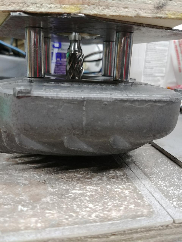  |
|
|
|
Post by 190mech on Dec 2, 2018 1:04:18 GMT -5
Go for it!Careful though,"That dog bites"!!  |
|
|
|
Post by 90GTVert on Dec 2, 2018 8:50:45 GMT -5
I would prob try it at ~8:1 and see how it does. Tough to put material back and it was running strong before. I don't really know the limits of corrected compression. I've been going by what has worked for me. For big 4Ts, dynamic compression of 8-8.5:1 is common and often considered a limit for pump gas.
|
|
|
|
Post by oldgeek on Dec 2, 2018 10:09:22 GMT -5
I would prob try it at ~8:1 and see how it does. Tough to put material back and it was running strong before. I don't really know the limits of corrected compression. I've been going by what has worked for me. For big 4Ts, dynamic compression of 8-8.5:1 is common and often considered a limit for pump gas. Yeah I thought about it overnight and came to the same conclusion. I am not 100% sure I have the template indexed the same way it was, and that could easily cause more to be taken away than I want. Hopefully this evening I will be able to clean things up and see how the squish is now. |
|
|
|
Post by oldgeek on Dec 2, 2018 20:14:19 GMT -5
I honed the cylinder a bit, cleaned up everything and put it together with no rings, no sealant and the head bolts just snugged up good so I could check the squish. It is anywhere from .59 to .73 That is not too bad compared to some other precision I have run across. By the time I add some sealant and some copper spray it will be good to go, I hope!
|
|
|
|
Post by oldgeek on Dec 14, 2018 21:28:30 GMT -5
Due to one thing or another I have not had much time for scooter work. Rain and cold have been a big part of the reason, and have also prevented me from getting any scooter rides in. I have been working on a solution to clean up the crank shoulder where the ramp plate sits. I previously mentioned there was some slipping going on there and as a result the shoulder on the crank is kankered up a bit. Actually, I think the shoulder was never cut flat in the first place so when I tightened the variator nut, the whole assembly never really clamped together well. I thought I had a picture of the crank somewhere before I did any repair work to it but I can't find it ATM. Here is a picture after I have already done a little work on it. You can see there is a chamfer on the shoulder of the crank, presumably to prevent damage to the crank seal when you install it. It would clamp a lot better if that area was completely flat. 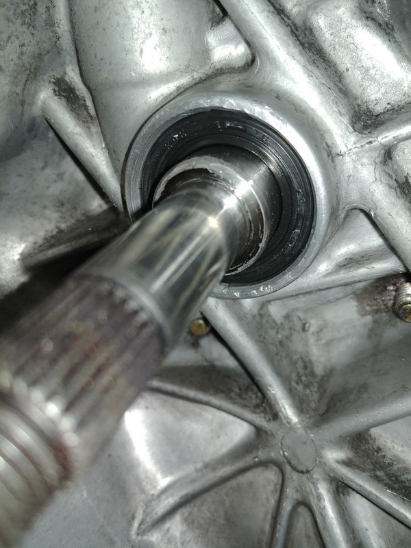 This is what I came up with to clean it up a bit so hopefully it can clamp the ramp plate tighter when assembled. I used an old restricted style variator bushing I had laying around, and cut some sticky backed sandpaper doughnuts to fit it and the 14mm crank. A 9/16" leather hole punch worked perfectly for the center hole, fits on the crank just right. 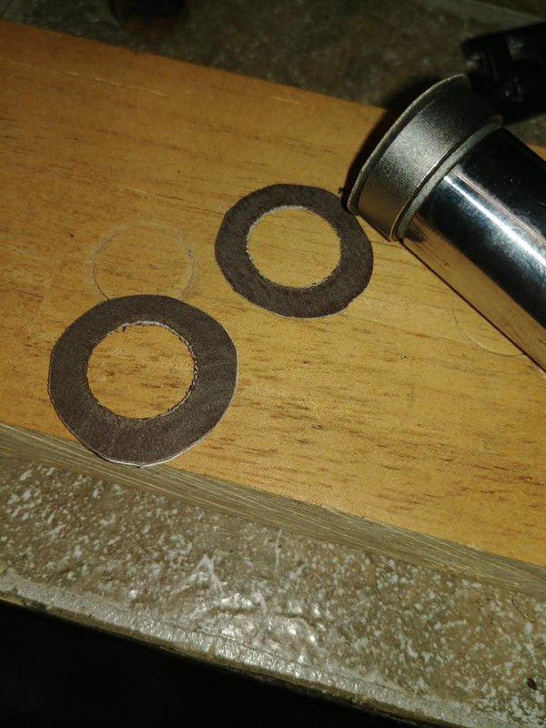 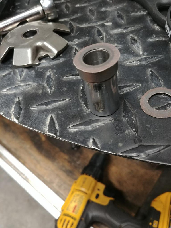 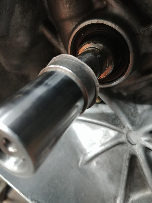 I repurposed a Trail Tech keychain to make a belt, and used an old bearing to put pressure on the bushing as the drill spins it.  I only had 400 grit sticky backed sandpaper, so I picked up some other grits on the way home and will finish the repair sometime this weekend, hopefully. I wonder if the plate would grip better if I left the shoulder rough textured a bit (220 grit), or would polished (400 grit) be better? This is what the ramp plate looked like after less than 50 miles I think.  |
|
|
|
Post by gsx600racer on Dec 14, 2018 22:32:45 GMT -5
Iv never seen a ramp plate & crank do that.  |
|
|
|
Post by oldgeek on Dec 14, 2018 22:49:27 GMT -5
Iv never seen a ramp plate & crank do that.  Massive torque from high compression?  It was tight the first time. The second time I tightened it without using the torque stick so it would be even tighter, it still moved. Almost like the shoulder was fractured a bit. Totally destroyed 2 cheap sets of glide keys in under 50 miles. Btw, I found some SEF plates, had to pay dearly for them though. |
|
|
|
Post by gsx600racer on Dec 14, 2018 23:19:43 GMT -5
Iv never seen a ramp plate & crank do that.  Massive torque from high compression?  It was tight the first time. The second time I tightened it without using the torque stick so it would be even tighter, it still moved. Almost like the shoulder was fractured a bit. Totally destroyed 2 cheap sets of glide keys in under 50 miles. Btw, I found some SEF plates, had to pay dearly for them though. I wonder if all the surfaces(drive plate/drive boss/ramp plate) were not parallel to each other and they were not making full contact with each other when sandwiched together. I get that you're making more powah, but just can wrap my head around the slippage. I know the pics make it clear that its happening. PS: Your ingenuity never ceases to amaze me.  |
|