


DIY CDI module build thread and ignition optimisation [PICS]
Oct 11, 2019 15:12:26 GMT -5
190mech, ryan_ott, and 5 more like this
Post by squab50 on Oct 11, 2019 15:12:26 GMT -5
Hi, this will be the DIY CDI build and optimisation thread, for harvesting more ignition energy from the original stator resp. charging coil. Feel free to show your own builds or ask if help is needed.
This is a good alternative for buying crappy black box "tuning" CDI's which does technically nothing fancy.
CDI (Capacitor Discharge Ignition)
All information and suggestions are from an austrian guy named Ewald. His homepage in german www.motelek.net
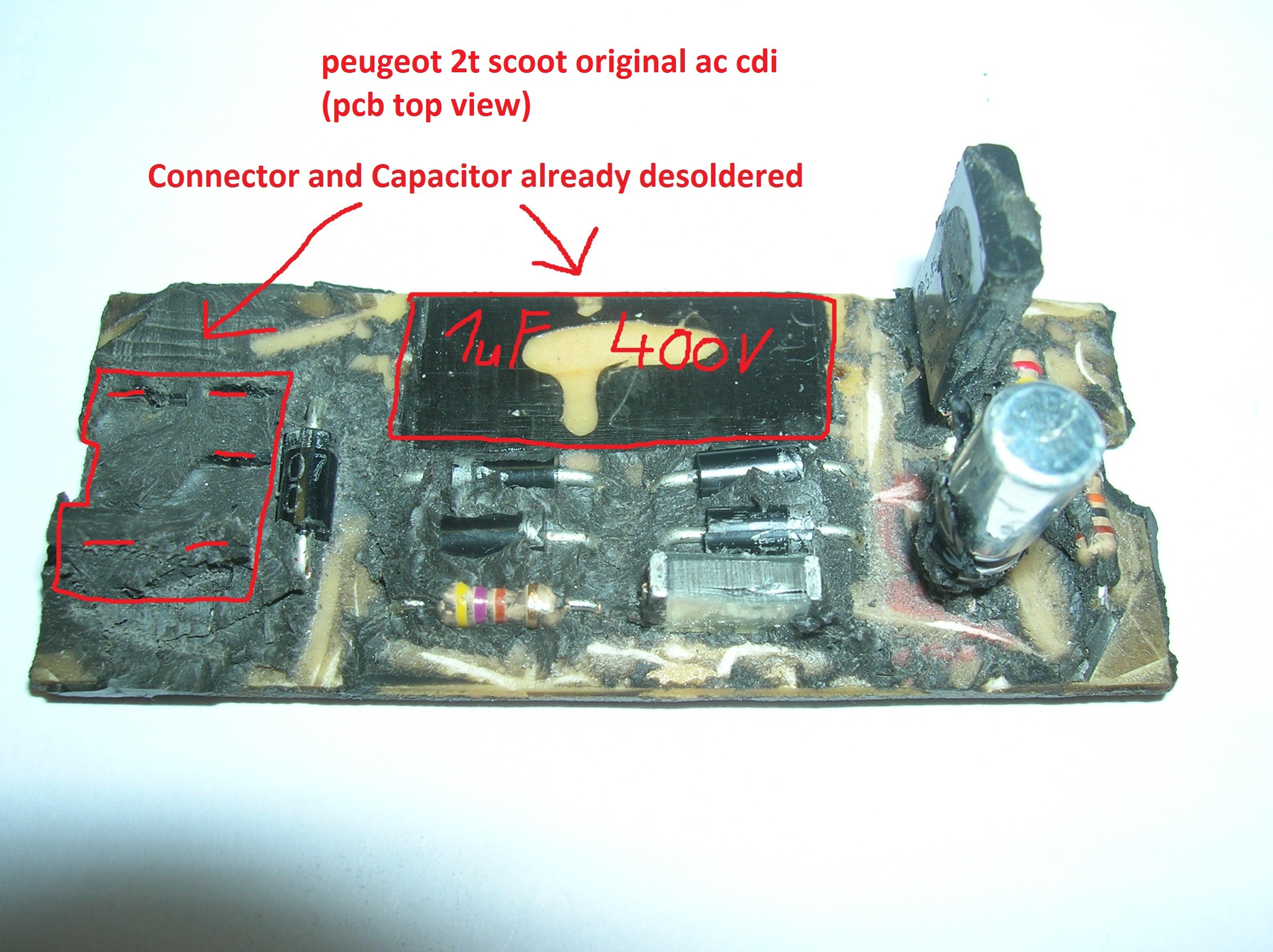
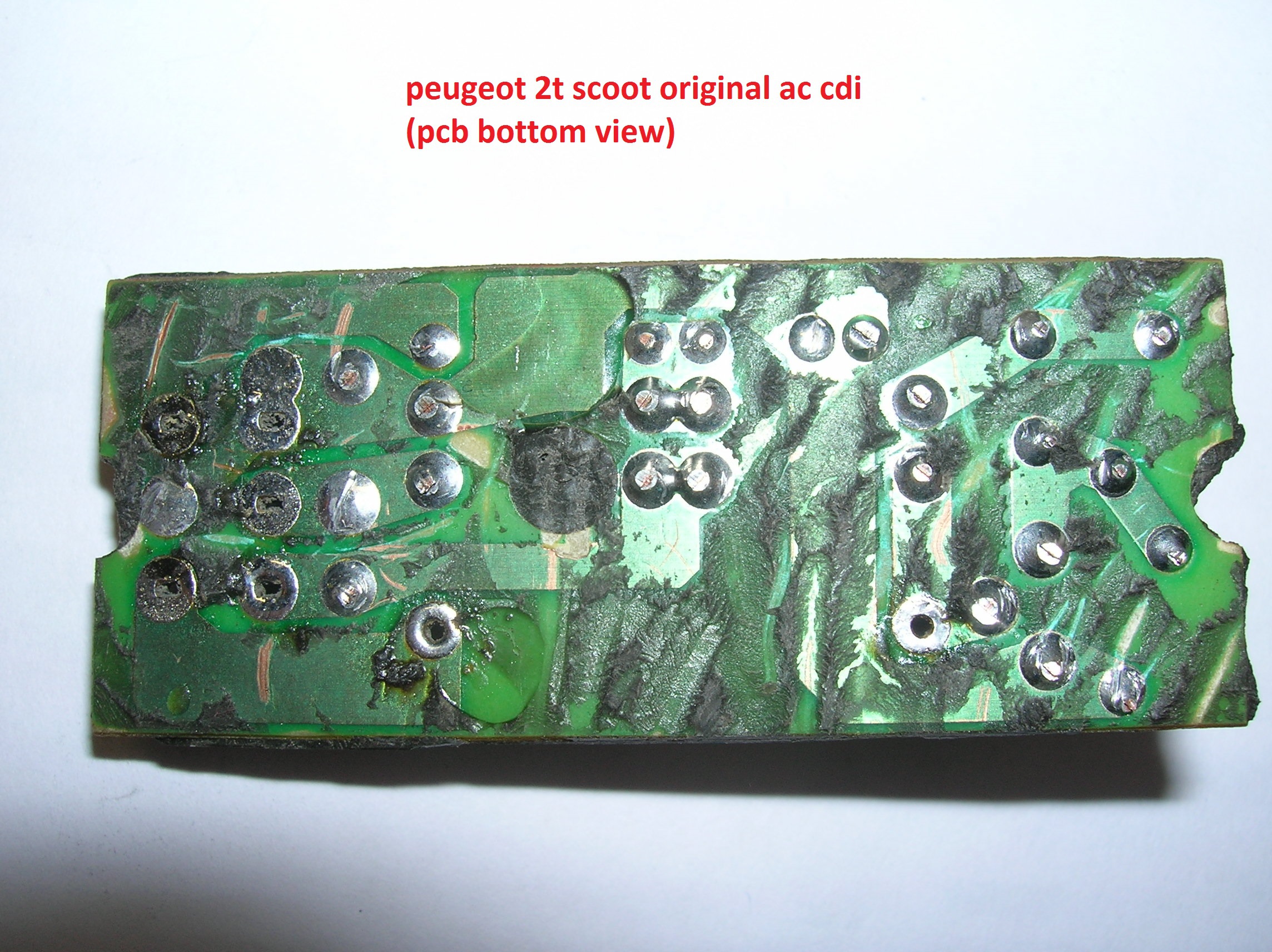
1. First we have to depott the original CDI module. Get a spare or a used one to work on. But always a CDI that works with your scooter or is designed for it. Be careful so you can read the component values. Better measure it if a multimeter or LCR meter is on hand.
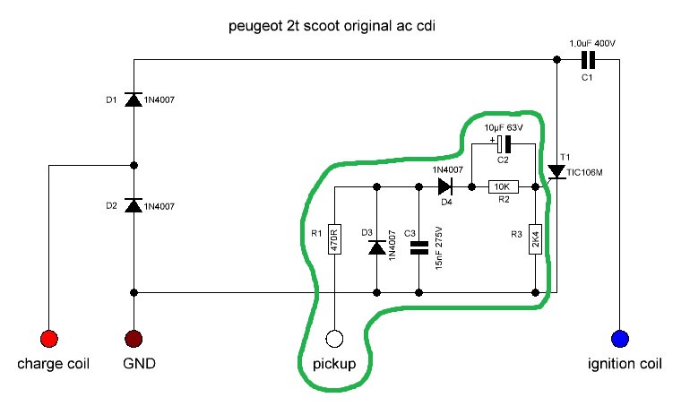
2. Draw the circuit diagram. The green marked part is for controlling the thyristor T1. It is also responsible for pickup signal conditioning, pickup rectification and ignition timing retarding. We will take this green part for our new CDI build so the new CDI will have the same ignition behavior as the old stock one.
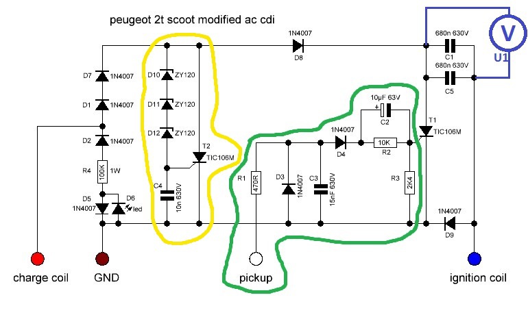
3. Draw the new circuit diagramm. Use what you have discoverd for your CDI's pickup part (green). Use your component values!
Draw the rest as shown in the picture below. Use this values. For C1 and C5 we have to test different capacities when testrun the new CDI as we try to match it/them to the charging coil. A 1uF 400V capacitor is good to start with. Always use an MKP foil type capacitor as it is pulse load resistant.
4. find capacitor size
But how to find the suitable capacitor/capacitors to use for C1 and C5 ? Well that depends on your needs. Your capacitor choice will determine where ignition energy can be delivered. A small capacitor is better for high rpm's, a big one for lower rpm's. We will look for chargeenergy per spark in Millijoule. As a rule of thumb it's said that all under 20mJ is bad.
Build your drawn modified CDI and hook up a multimeter U1 on the capacitor C1C5 as shown above. Select 600V DC voltage range.
Start with a 1uF 400V capacitor (MKP foil type). Then start your engine. Scooter is on kickstand so you can rev it.
Go through the rev range and write down the voltage reading(Veff) every 1000rpm.
Here's a ms excel table which does the calculations for you --> filehorst.de/d/dfCftyby
Just put in the voltage readings you wrote down and your selected capacitor size.
Do this for your old depotted CDI too, just to compare and see your improvements.
A table for 2x 0,68uF capacitors on a peugeot 2T scoot can look like this. 500, 1000 an all above 10000rpm's are not measured.
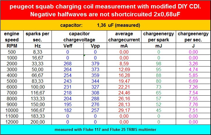
As you can see sparkenergy is very good. From 98mJ to 45mJ though the whole rev range.
At 2000rpm the sparkenergy is limited to 98mJ because the thyristor crowbar(voltage limiter) kicks in around 380V (Vpp).
The limiter is marked yellow in the modified circuit diagramm and is set by D10, D11 and D12. These are 120Volt zener diodes. It protects the capacitor from overvoltage, especially at idle where not much energy is needed, voltage tends to climb up.
But why did i choose 2x 0,68uF here? Thats because it suits my chargecoil best. I've also tried 4x 0,33uF but it doesn't change voltage much.
More capacitors in parallel give lower ESR (equivalent series resistance). It "can" help to get more voltage in the cap when the chargecoil gives it's pulse. But can also be worse. You have to try out. For paralleling always use cap's of the same capacity and voltage.
Remember that we will always! see an improvement in sparkenergy, whether we adapt the capacitor or not. That's because negative halfwaves are no longer shortcircuited due to D2. So the magnetic flux isn't collapsing anymore--> More power on positive charge pulses. The chargecoil does less work because there is no load when negative halfwave occures.
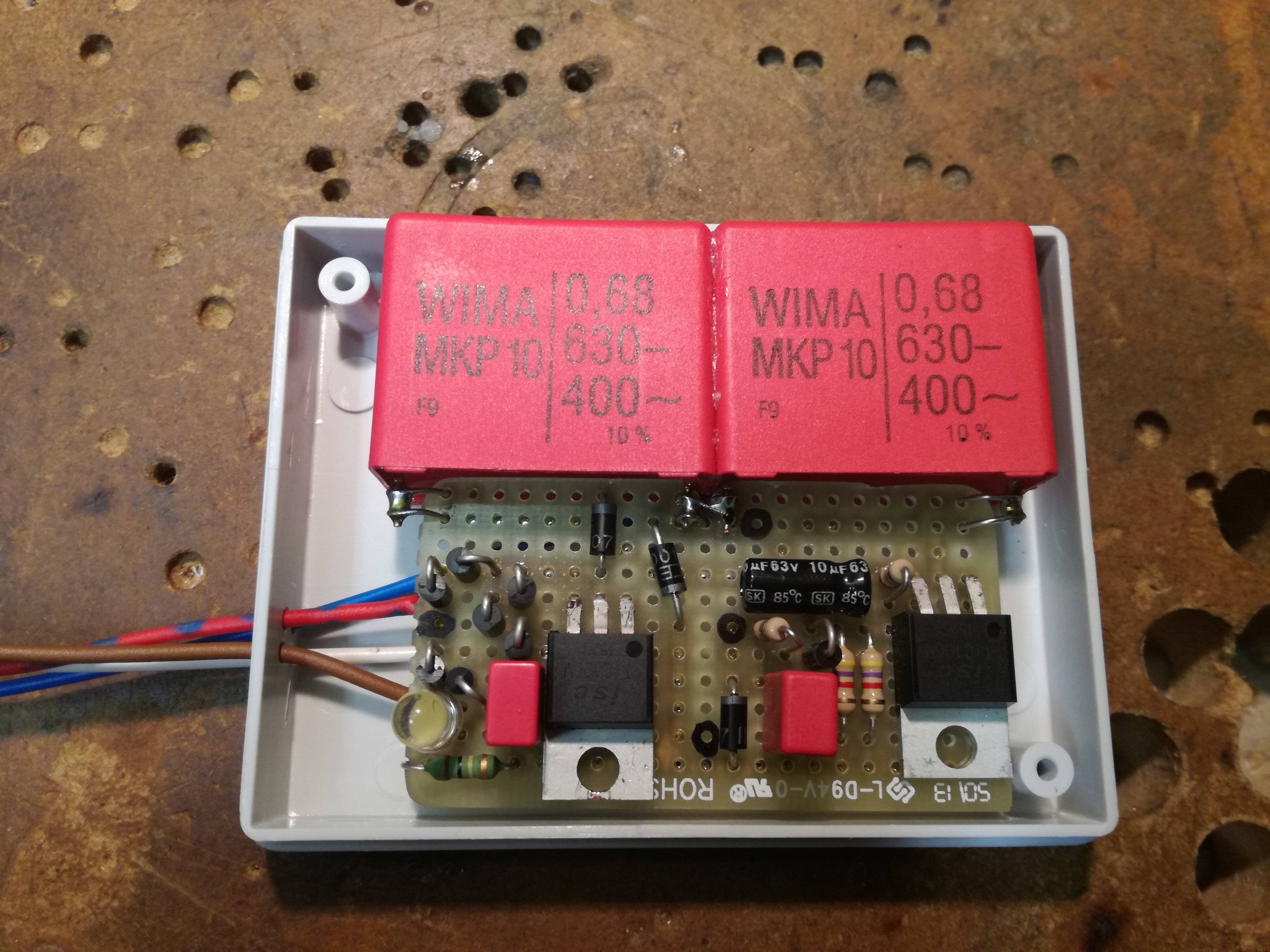
Modified DIY CDI before potting.
to be continued -->>


 , it would be cool if someone is interested and maybe will try to build one on their own.
 No tuning inside


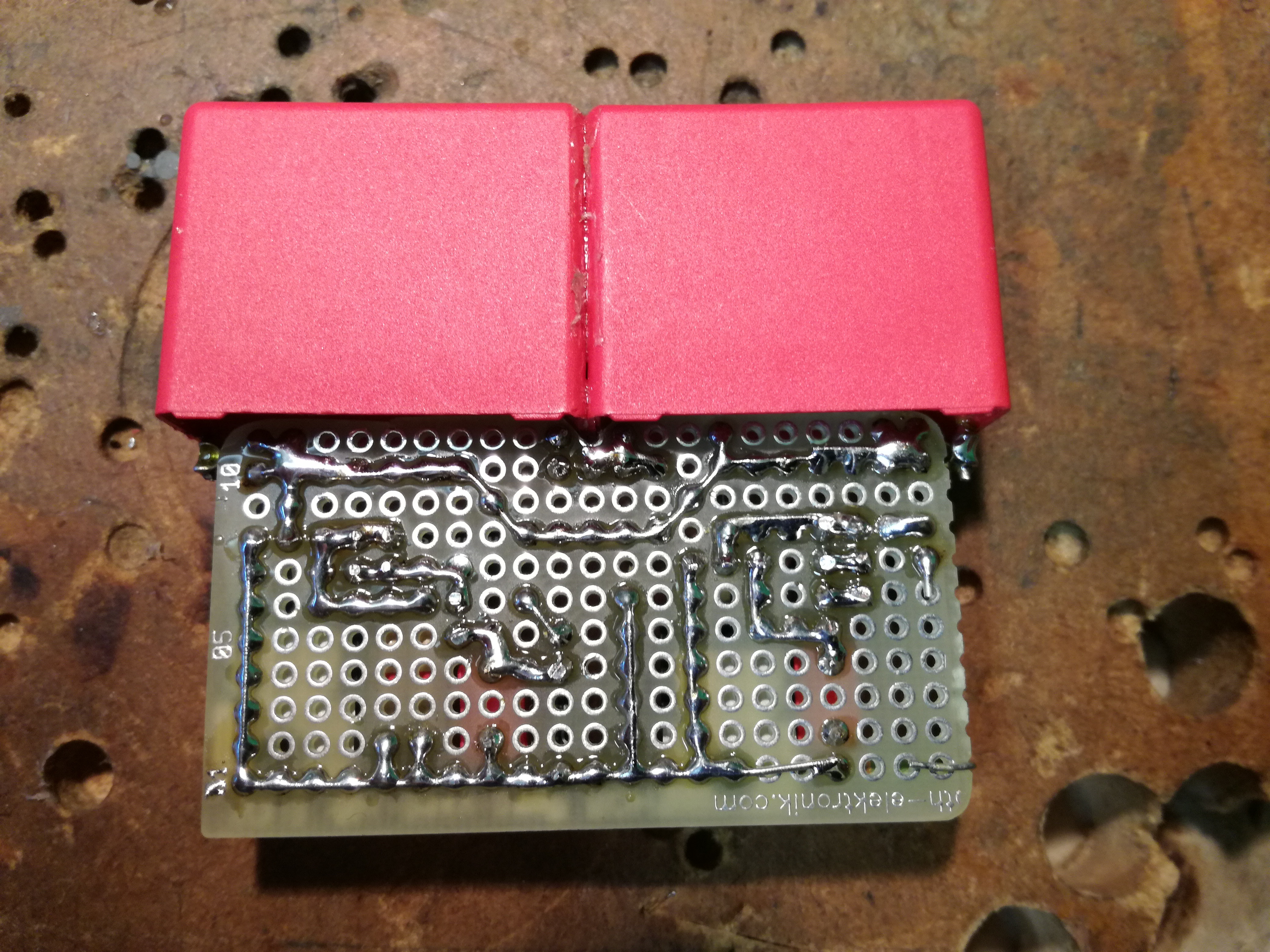
 And as you can see, it's also ROCK SOLID!


