|
|
Post by waltinhawaii on Sept 9, 2013 11:13:11 GMT -5
thanks John. It is good to have the grinder back in use to be able to finish this thing. Funny, I bought the pencil grinder and the 90 degree at the same time, and never used the pencil grinder yet, even though the pencil was far more expensive (like twice the price).
The exh sub ports are strange, they are actually just half holes, the outer margins are pretty much just divots which are right over the stud tunnels so can't relieve the metal there very much, might break through into the tunnel. I expect the sub exh ports to fill very quickly with carbon in use, this cylinder will probably require frequent decarbonizing with a pick tool. Not sure its worth it, the standard single exh port may work just about the same. I think for real power, it may be better to get the single exh port and just extend the port sideways to near 80% chord width or so and just add your own bridge in the middle.
|
|
|
|
Post by kevin55950 on Sept 9, 2013 11:45:48 GMT -5
I have aux ports on my MVT cylinder. I'll try to take a picture of those, they are made pretty well IMO. That might give you some ideas.
|
|
|
|
Post by waltinhawaii on Sept 10, 2013 5:55:03 GMT -5
Thanks, Kevin, would appreciate the pics. I have tried to widen the holes very slightly in my aux exh ports, but the existing holes are TINY and difficult to get any tools in there. The holes are as-cast and not straight, either. Tonight I did a bit more housekeeping and cut the top edge of the cylinder a tiny bit, about a 1/4" or so, just enough to unshroud the path to the trench. Left side: 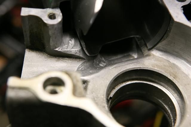 Right side: 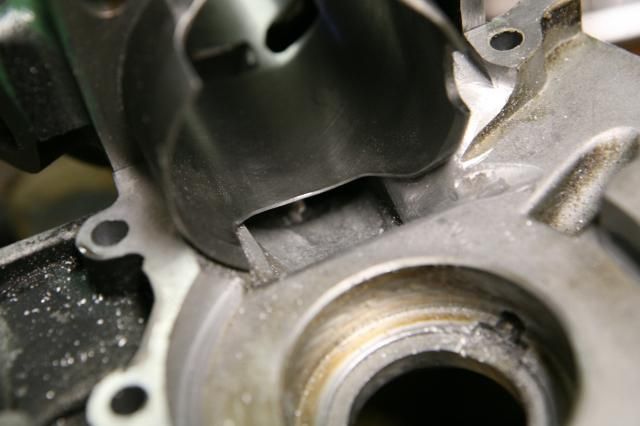 |
|
|
|
Post by waltinhawaii on Sept 18, 2013 23:24:44 GMT -5
I've had a few 'false starts.' I heated up the cases to about 200 degrees with a heat gun, then dropped the frozen crank/bearings into the heated case... and it sat on the surface, slightly crooked. difficult to move, but I tapped it back and forth with a plastic mallet with no luck. After bracing under the hot case with a can of paint and hammering the top of the crank with the plastic mallet (not too hard, don't want to whack the crank out of true), the crank refused to budge and I ended up with a very sweaty crank, some partially drying silicon on the case half, and a misaligned and thoroughly pissed off crank. After cooling the case, I used the case separator to pop the partially inserted crank and checked the bearing surface for any damage but it was fine. Then I had to razor off the silicon. This happened a couple times and left me discouraged; it occurred to me that it might have been easier to put the frozen bearings into the hot case and then freeze the crank itself and put it into the hot bearing/case but hey, too late now. Bearings were on already. The problem with hammering on the crank is that it is only pressed together and you can't afford to hit it hard or shock it as the crankpin is offset in the crank web. But, what if you supported the other side of the crank web? so that you could press downward on the end of the crank really hard and not be worried about the crank pin moving out of alignment? So I measured the space between the crank webs and got .286" (the space in the middle of the crank). I then machined a steel plug: 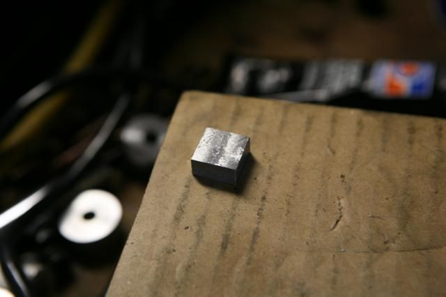 which was EXACTLY .286" in thickness and inserted it into the crank, on the opposite side of the crank pin: 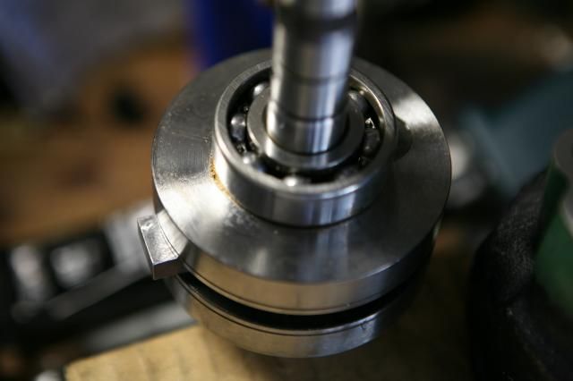 I then set up the case half into the press with the now fortified crank: 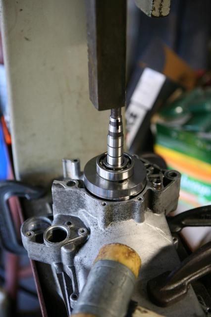 At this point I was going to take the crank out and heat the case a bit then put it back to press the crank in, but thought what the hell, the case separator pulled the bearings out easily enough without heating... so just pressed it in: 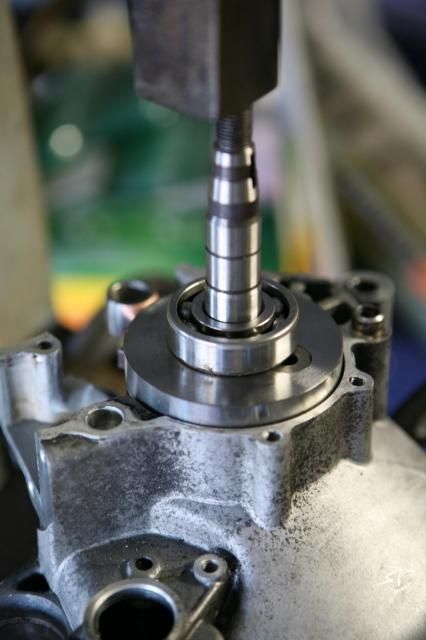 All done. Just reached in and took out my block from between the webs: 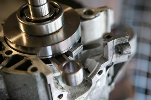 that was easy enough. Now I have to apply silicon to the other side and press it onto the completed side same way. But its dinner time so I'll save that for later. Man, I been struggling with this for a few days with those false starts... it's not that hard. But I guess my cases are just super tight, this engine has not been apart before and the bearings are super tight into the cases, no matter how much I heated it up, the would not go in straight. But with the press it seemed just a couple seconds was enough.... what a difference. |
|
|
|
Post by 190mech on Sept 19, 2013 4:42:38 GMT -5
I hate it when that happens!My case had too much epoxy in it to put the heat gun on so I tapped the bearings in the cases and fabed up a puller to pull the shaft thru the inner race.I'm super spooked about putting any pressure on a crank end as I've seen many tweaked cranks that were pounded in!!
Another method that works well is tap the bearings in the cases,then throw the heat gun on the inner race till its hot and drop the crank in..Brent has a vid somewhere on here about this..
|
|
|
|
Post by moofus02 on Sept 19, 2013 4:44:44 GMT -5
I'd leave that spacer in till both sides were togather
Sent from my SPH-L720 using proboards
|
|
|
|
Post by waltinhawaii on Sept 19, 2013 10:51:39 GMT -5
Hahahaa! John, that's exactly what I was thinking... designs for a puller to pull the end of the crank through from the other side have been flying through my head. I was actually going to use the case separator, and just fabricate a widget to screw onto the end of the separator's big center ram that would lock onto the end of the crank. Problem is, both the crank and the separator have metric threads and I have only imperial taps and dies and my lathe can only cut imperial as well  Believe me, I used LIGHT pressure on the press. It's an arbor press (gears, no hydraulics, much better feel). I was spooked about using any pressure too, in fact using the plastic mallet made me wince. Maybe I should have run a small tack weld on the ends of the crankpin first to ensure it didn't move, occurred to me but I didn't think I was going to get any serious muscle into it so dismissed it as too much work. If my bike shimmies the first time I start it up I'll buy you a dozen donuts and take the bus from now on  Moofus, that thought also occurred to me  I have to put the block back in order to finish putting on the other case half. I was also curious about how well the crank had been balanced out in stock form and was going to set it up in V blocks and measure the runout prior to installing it, but fabricating some kind of puller to pull it through from the other side got top priority so that project fell by the wayside. Sorry, no time for that, just have to assume it's close otherwise they wouldn't have sold it to me. (I know, I know, probably not a good assumption to make) I've seen pretty badly out of spec 'new' parts. |
|
|
|
Post by waltinhawaii on Sept 19, 2013 10:55:48 GMT -5
Oh, my old tube of copper/silicon/gasket RTV material was dried up and useless. I have a tube of normal black silicon which is still wet/soft; is that ok? Or are people reporting leaks from the cases if you don't use a particular sealant?
|
|
|
|
Post by 190mech on Sept 19, 2013 11:22:32 GMT -5
The normal silicone should do fine..I like the Ultra Gray and also Ultra black is tough too..
|
|
|
|
Post by moofus02 on Sept 19, 2013 11:23:02 GMT -5
I've seen Pickel fork like tools that go around the small end of the rod and into the crank across from the crank pin to hold the crank true during assembly but I like John's idea of chucking the crank in a lathe and polishing it so it floats in the bearings makes assembly easier and let's the crank self center. Makes me wonder if that would effect the crank seals?
Sent from my SPH-L720 using proboards
|
|
|
|
Post by waltinhawaii on Sept 19, 2013 22:06:39 GMT -5
John, got any pics of your crank pulling tool? I ran a couple designs in my head, till I settled on using the separator tool in reverse.
|
|
|
|
Post by 190mech on Sept 20, 2013 4:40:02 GMT -5
Walt,Its too ugly to show the world!I welded a 10mm nut on the end of some 5/8" redi-rod and used a piece of steel tubing a bit larger than the crank end to pull it through,,
I have adopted polishing the crank journals for a snug slip fit since then as Jan Thiel suggested on another forum..
John
|
|
|
|
Post by waltinhawaii on Sept 20, 2013 11:09:18 GMT -5
Using a piece of threaded rod is a great idea, John. The amount of force I used on the press was very slight, so any threaded rod would do, 1/2" would be fine. Polishing the journals, huh? What if the crank slips inside the inner race? it would then function as a plain bearing, I guess, compounded inside a ball bearing. I guess that would serve the function of dissipating wear over 2 elements instead of 1, so might actually be beneficial...unless you don't want the crank journal to be exposed to wear (i.e., you intend on replacing crank bearings but expected to re-use the crank itself). In my experience they both normally get replaced anyway on machines of this size and they are cheap, so yeah, I can see that. Hmmmm, something to consider for next build. Let's see... tape up the conrod and chuck up the crank in the lathe to polish the journals?
|
|
|
|
Post by waltinhawaii on Sept 21, 2013 0:53:30 GMT -5
Well the crankcase is together and the silicon should be cured by now; but the crank seems to be binding slightly as I spin it. I think I will put together that puller after all and see if that helps things. In the meantime, I put the piston about where BDC would be to see if the intake cutout needs help: 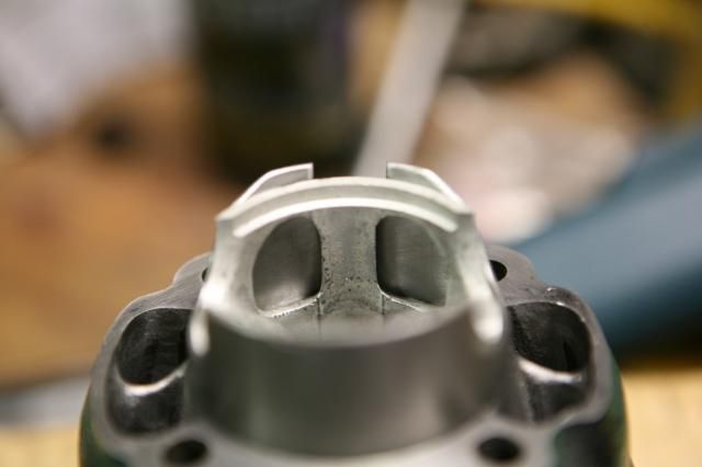 The cutout in the cylinder looks like it could be wider, but the depth looks like it will be about right; any farther up and the top of the piston will close off the ports before any air can move through it (I think). However, at TDC, this is what I saw: 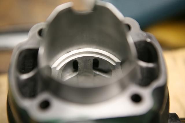 So, I don't get it. If the windows in the piston never see the bottom cutout and barely see the boost port before TDC, Why are there 2 windows and why are they so wide? There should just be 1 window there, not 2. I think I should narrow the bridge between the 2 windows (widen them inward toward each other slightly), but this part doesn't make a lot of sense, other than to provide a bit of cooling airflow to the piston crown. Has ANYONE really empirically noticed any difference in power by modifying the cutout on the cylinder or the holes in the back of the piston? |
|
Rune 75
Scoot Enthusiast
  
Posts: 441
|
Post by Rune 75 on Sept 21, 2013 4:00:15 GMT -5
To loosen up the crank you need to slap it on both sides whit a rubber mallet, it will take the tension out of the bearings. That way you can also center the crank in the case/housing.
|
|