|
|
Post by oldgeek on Dec 2, 2015 21:37:11 GMT -5
I have previously mentioned that I would like to have an android based configurable dashboard for my scooter to display things like speed, RPM's, temp, or whatever. I was thinking of using bluetooth to connect the sensors to the android phone. I stumbled onto a few apps for the smartphone that use data from the OBD connection in cars and allow you to create a customized display of the data on your phone. The OBD data is transmitted to your phone by a inexpensive bluetooth dongle plugged into the OBD connector of your car. Evidently this technology has been around for a while already. I used to be current on gadget, electronics type stuff but I am waaay behind these days. Anyway, from the very little research I have done so far, the OBD data interface is Canbus (controller area network) based. In theory one of the bluetooth OBD dongles should be easy to hack for our scooter needs. I have not used the Canbus protocol before, but I have used other 2 wire protocols that are similar to the Canbus in my past work in electronics. I invite anyone who would like to help out with this project to post in this thread. I need all the help I can get. I think it could be done pretty cheaply, and who wouldn't like a custom dash for their scooter project? I was going to go ahead and order a OBD bluetooth dongle because they are so cheap, but I will wait to see if anyone here has experience with them before I do. I will place accumilated links for the project here: ODB bluetooth dongle , Wiki CAN bus |
|
|
|
Post by oldgeek on Dec 2, 2015 22:16:10 GMT -5
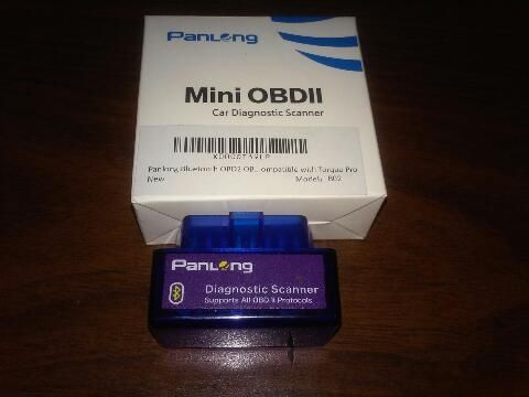
I decided to order this ODB bluetooth dongle from amazon for $12.99 It has decent reviews, and supposedly works with the free android app I am going to try out called Torque lite, they also have a paid version, Torque Pro that currently costs $4.99. There is also a WiFi connected version of the ODB dongle for IOS users, so you Apple guys are covered! The phone I am using for this project is an old Nexus-S I have laying around that the telephone part does not work on, but everything else does. There is no need for the phone to be active with a carrier for our use. So any android phone you may have laying around should work for this project. |
|
|
|
Post by Lucass2T on Dec 3, 2015 1:37:33 GMT -5
Do you know how the data from the engine sensors are translated so the OBD connector is useable? Is there an ecu involved? You'll need something (ecu) that can read the tiny currents that the sensors emit right? An OBD connector is nothing more than a connector to read the engine management system (on cars) right?
|
|
|
|
Post by oldgeek on Dec 3, 2015 7:22:09 GMT -5
Do you know how the data from the engine sensors are translated so the OBD connector is useable? Is there an ecu involved? You'll need something (ecu) that can read the tiny currents that the sensors emit right? An OBD connector is nothing more than a connector to read the engine management system (on cars) right? You are correct. I will add that the OBD connector on a car is a connection point to the CAN bus network. Which means it can communicate or listen to all the traffic on the CAN bus network. The wiki explains it much better than I can, scroll down to applications. Wiki CAN bus |
|
|
|
Post by Lucass2T on Dec 3, 2015 8:59:59 GMT -5
Do you know how the data from the engine sensors are translated so the OBD connector is useable? Is there an ecu involved? You'll need something (ecu) that can read the tiny currents that the sensors emit right? An OBD connector is nothing more than a connector to read the engine management system (on cars) right? You are correct. I will add that the OBD connector on a car is a connection point to the CAN bus network. Which means it can communicate or listen to all the traffic on the CAN bus network. The wiki explains it much better than I can, scroll down to applications. Wiki CAN bus But how are you going to, or with what are you going to collect and translate the signals from the different sensors you are going to use? You'll need some sort of computer or a programmed PIC or something? Canbus is as far as i understand to reduce the ammount of wiring since two or more ecu's/computers (controlling each ther own component) can communicate with each other though some sort of binary signal sent (both ways) over a single wire....in stead of a bunch or wires which are used for their single own purpose. In a canbus system you can encounter (on one single wire) all sorts of signals from different components communicating with each other? Sorry for all the questions...but im really interested in this stuff |
|
|
|
Post by oldgeek on Dec 3, 2015 12:06:00 GMT -5
But how are you going to, or with what are you going to collect and translate the signals from the different sensors you are going to use? You'll need some sort of computer or a programmed PIC or something? Canbus is as far as i understand to reduce the ammount of wiring since two or more ecu's/computers (controlling each ther own component) can communicate with each other though some sort of binary signal sent (both ways) over a single wire....in stead of a bunch or wires which are used for their single own purpose. In a canbus system you can encounter (on one single wire) all sorts of signals from different components communicating with each other? Sorry for all the questions...but im really interested in this stuff Yes, depending on which sensor you are working with, there will be a signal translation of some sort. I will have to dig deeper to find out, but this should be fairly easy to get done at least for some sensors. There is an inexpensive CAN bus controller/transciever chip set that takes care of all the legwork of connecting to and communicating with the CAN bus. I need to find out what the CAN bus chip set wants to see at its input and how it wants it to be formatted, it could be serial data, or analog or? I have not gotten that far yet. For instance, speed and RPM should only need a pulse counter such as a Hall effect switch or optical, connected to a CAN bus chip set. There may be a need for signal translation between the pulse counter, and the CAN bus chip set. which may be as simple as just a few components or as much as a PIC. Another example is a temp sensor using a type K thermocouple connected to a module that takes care of the signal conditioning and temp compensation associated with a thermocouple, then it outputs an analog 0 - 10 volt signal to be fed into the CAN bus chip set. IMO the hard work is already done by the android app developers and the OBD bluetooth CAN bus adaptor. The rest MAY be fairly easy to do for a GOOD electronics guy. So if one shows up here we are good to go, otherwise it will take me a while to sort it out. I am known for being slow  |
|
|
|
Post by Silar on Dec 3, 2015 18:43:15 GMT -5
I'm interested in this also. I currently have a bluetooth ELM327 interface and it works pretty darn good with android or a PC to look and clear OBDII codes and see current data... That is of course with cars and trucks. Like others have said, it may be a bit different in interfacing with a scooter since there is no controller you are connecting it to. I'm actually a programmer by trade in the oil and gas industry and do all the programming for our PLC's and PAC's, control systems, SCADA systems, etc.. I'm curious as it's not just going to take a good electronics guy. You are literally going to have to develop a controller from scratch.. It's not like a signal is on a specific pin. It's almost like a serial RS-232 interface in a way as the data is interpreted by the scanner..  |
|
|
|
Post by Silar on Dec 3, 2015 18:55:18 GMT -5
It may actually be easier to develop a bluetooth controller to bring all the signals into, then create the app to read the data over bluetooth. Something like this may actually be beneficial for the auto guys also.. Here's a great document that explains quite a bit with the OBD2 interface though... www.lbcc.edu/attc/documents/OBD2.pdf |
|
|
|
Post by oldgeek on Dec 3, 2015 21:44:08 GMT -5
I'm curious as it's not just going to take a good electronics guy. You are literally going to have to develop a controller from scratch.. I disagree, I believe it will be much simpler than that. But I have been wrong before  The signal we are interested in is actually on two pins, 6 and 14 with pin 5 used for signal ground. CAN bus is a balanced differential communication scheme that uses a twisted pair of wires. The twisted pair helps reject induced interference on the line and is great for RF noisy environments like cars and industrial automation settings. Pin 16 will be supplied with +12 volts from the scooter battery to power up the bluetooth module, and pin 4 is the ground. Each sensor output will be connected to a separate CAN bus controller/transceiver chipset. A single twisted pair of wires will daisy chain between each CAN bus chipset and ultimately be connected to pins 5 and 14 of the Bluetooth dongle. Then the android app should be able to display the information on the smartphone. Several details still need to be worked out, and there may be some programming of a PIC style micro controller to translate the data from the sensor to the CAN bus chipset which I believe is looking for serial data stream.  That being said, I am NOT a programmer. Although I did do a sizable amount of programming in Pbasic, a type of BASIC used by Parallax in their microcontrollers, but that was only because I HAD to do it. Programming is like learning a foreign language, and is not within the scope of my abilities. I was a practical electronics guy in the past. I have worked on a vast amount of electronic stuff such as two way radios, amusement park ride control systems, high end lighting and sound, video games, computers and computer networks to name a few. I am a master of nothing, but a jack of many. Now days I fix heating and cooling systems to pay the bills. If you are correct then this project is over for me, because it will require much more effort and smarts than I have left in me. Would you be willing to take a crack at programming a PIC or adruno microcontroller if it is necessary for the sensors? |
|
|
|
Post by oldgeek on Dec 3, 2015 21:55:12 GMT -5
It may actually be easier to develop a bluetooth controller to bring all the signals into, then create the app to read the data over bluetooth. That is basicly what I am proposing, except I want to use the existing bluetooth dongle to bring the CAN bus data to the Android app to display. CAN bus is a multi master protocol, but i think it would work in a polled mode like RS485 if we need it to. |
|
|
|
Post by Silar on Dec 3, 2015 23:26:04 GMT -5
It may actually be easier to develop a bluetooth controller to bring all the signals into, then create the app to read the data over bluetooth. That is basicly what I am proposing, except I want to use the existing bluetooth dongle to bring the CAN bus data to the Android app to display. CAN bus is a multi master protocol, but i think it would work in a polled mode like RS485 if we need it to. Actually it's comms is much like RS485 half-duplex. A,B, and c (ground) or +,-, and ground. I'm not saying it can't be done. I'm just saying it may be much more difficult than you may realize. What I was saying before, was to create a controller where inputs will be brought in from each sensor directly, and with bluetooth talk to a custom app created.... Using an OBD2 compliant interface just to provide bluetooth functionality to an already existing app seems like going in a round about way for me and over-complicate something that may actually be easier to achieve. If it was me, I would create a controller with bluetooth capability with inputs for sensors and a custom android or ipad app for the interface. That would allow you to completely omit any interfacing through OBD2.. Just my 2 cents..  I'm definitely up for working on something though! |
|
|
|
Post by oldgeek on Dec 4, 2015 7:20:32 GMT -5
If it was me, I would create a controller with bluetooth capability with inputs for sensors and a custom android or ipad app for the interface. That would allow you to completely omit any interfacing through OBD2.. That is how I originally wanted to do this, except I was going to use bluetooth to connect each sensor individually to the android app. I believe you can have up to 7 bluetooth devices on a single network. When I stumbled across the bluetooth OBD dongle I changed my strategy. It may be my laziness trait talking, but I see no reason to develop a custom android app (something I could never do on my own) and design and build a controller when I MIGHT be able to use stuff off the shelf to accomplish the same thing. I appreciate you offer of help, and I am pretty sure I may need it. If you have time and would like to check out PIC or adruno style microprocessor programming by all means go for it. The most basic, cheapest PIC should fit the bill for what I need done. No rush at all, as I move pretty slow except when I am on my scooter.  |
|
|
|
Post by oldgeek on Dec 5, 2015 22:50:02 GMT -5
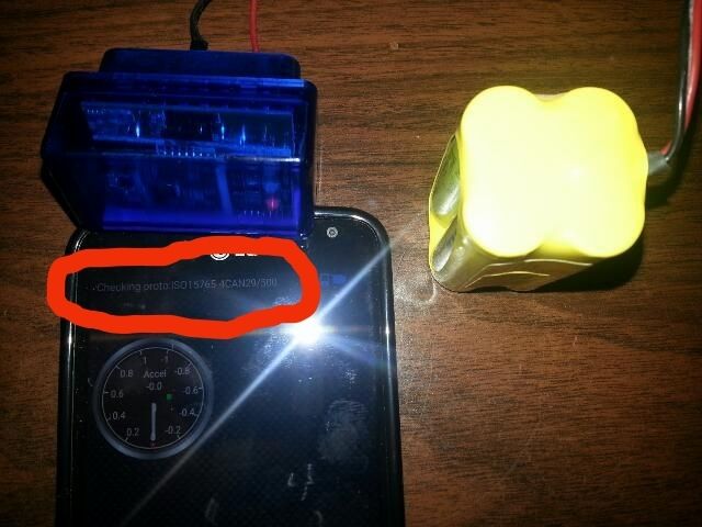
The mailman delivered the OBD bluetooth dongle I ordered from Amazon today.  I got home from the warehouse late this evening, but I wanted to see if I could get it setup in my work van. I plugged the dongle into the OBD connector under the dash board in my van, then I started the Torque lite app on my android phone. I was connected via blue tooth to the dongle and pulling data from my van in less than 2 minuets. Since that worked, I unplugged the dongle from the van, brought it inside, and connected the dongle to a small battery pack on my desk. I connected the red wire from the battery pack to pin 16 on the dongle and the black wire from the battery pack to pin 4 on the dongle. As soon as I started the Torque lite app on my phone it connected to the blue tooth dongle and started scanning for protocols.  Since the dongle is not connected to anything but power, this is as far as I can go for now. I have not yet ordered any of the CAN bus communication modules from China. The next step is to wire the data lines from a CAN bus communication module to pin 6 and 14 on the blue tooth dongle to see if they will talk to each other. |
|
|
|
Post by oldgeek on Dec 7, 2015 21:13:40 GMT -5
I went ahead and paid $4.99 for the Torque Pro android app. It has lots of cool features. I have it all hooked up to my work van for now, just to play with it. I still have not had the chance to order any Can bus modules yet, there just is not enough time in the day.
|
|
|
|
Post by oldgeek on Dec 8, 2015 21:39:57 GMT -5
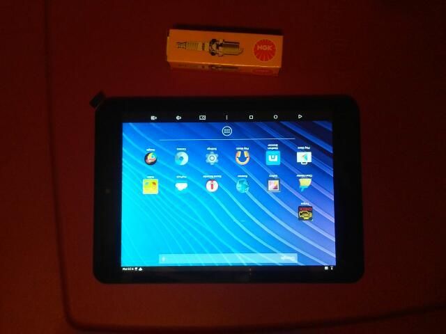
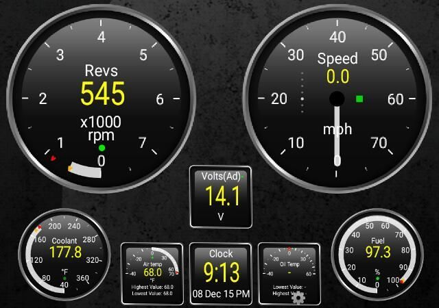
I was in Sams Club the other day and saw a NuVision 7.85" Android OS based tablet. The price was only $69.95 . Today I got to thinking how well one of those cheap tablets might work as a digital dashboard on a scooter. So I bought one this evening to see how it works with the Torque Pro app.  And a screen shot of a quick dashboard I created for my work van.  So far it seems to be a decent tablet for the price. It is a little on the heavy side, and I dont know if the screen will be visible in the sunlight. Also the cameras leave much to be desired, but poor cameras will not affect what I am doing with it. So far I have about $95.00 in this project. Even if I am not sucessful in getting it to work on the scooter, it is a blast to play with. |
|