|
|
Post by 190mech on Jul 22, 2014 18:43:50 GMT -5
Here is a bit of info on pipe building I've gathered over the years,, A Graham Bell has a great book on two stroke tuning that has a wonderful chapter on pipe building.If you dig around on the web it can be found in a PDF.. Here is a good pipe calculator right here on this forum,it uses Bells ideas and yields a good pipe with data from his book; 49ccscoot.proboards.com/thread/1317/tuned-pipe-calculatorHere is another calculator thats more geared toward the stronger MX and road race stuff,its said to be from the work of the famed 2T tuner Frits Overmars; users.telenet.be/jannemie/FOS%20PIPE%20black.xlsmThe best way to build a good pipe is start with a great design and copy it!Much info is on the web and a lot is junk,but there are some good drawings to be had.. Brent sent me the specs off his lowly MRP pipe years ago which I copied and was impressed by its power from such a simple design; 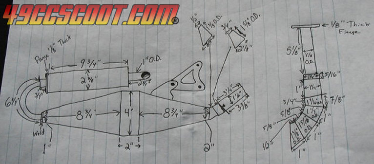 If you are more into the high end stuff the Yasuni pipes are great designs,here are some examples; The Yasuni C21, 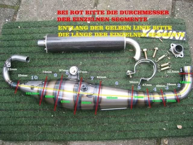 The Yasuni C16 posted by Josh from ScooterInvasion; 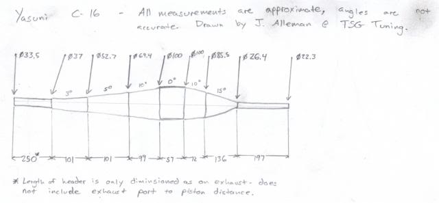 Here is one of my favorite designs,The Yamaha RZ 500-4 road race kit pipes,note the multi angle cones yielding a very smooth pipe; 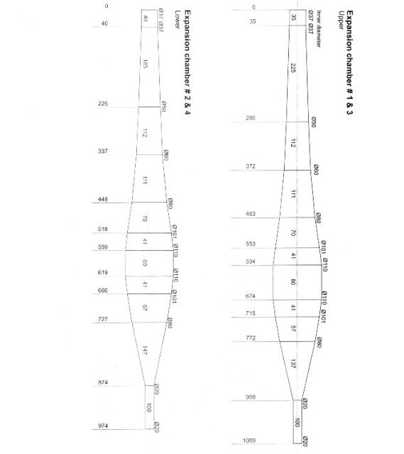 |
|
|
|
Post by 190mech on Jul 24, 2014 18:45:20 GMT -5
Cones can be fabed out of 20 gauge sheet steel,Old washers and dryers are a good place to get free sheet metal; 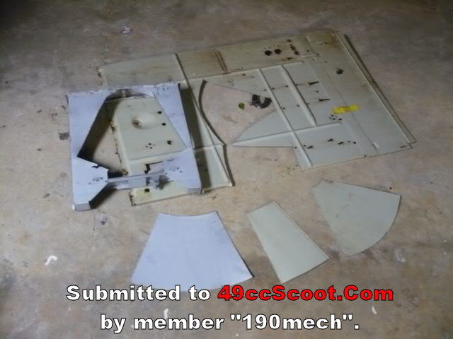 Cone calculators are online too and make perfect patterns; www.conelayout.com/Thought we'd work from the front to back..The all important head pipe;tapered is the way to real power,but a bear to fabricate!A 1.6 degree headpipe gives a nice boost over a straight one and well worth the extra effort..The 1.6 degree setup could be calculated and entered into the cone program,then the pattern cut out,rolled,welded,now we have a straight tube that'll fit nothing!The "cut and flip" method works OK(saw the tube at an 8 degree angle,flip it over 180 degrees and we have a 16 degree bend..I prefer to do a card stock full scale drawing and do the "cut and flip" method with it(a lot less work!!).Here is a quad pipe I built and the patterns; 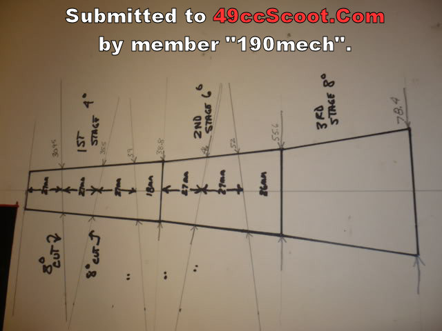 And after the cut and flip; 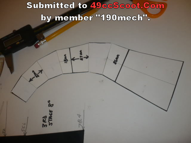 This gives a good visual look at the planned bends and can be adjusted if it doesnt fit well.. Once we are happy with it,the pieces are measured for length and diameter and entered into the cone calculator,nice small angled cone patterns result which are cut from sheet metal and welded together.. Here is a PeacePipe headpipe and 1st stage diffuser using this method; 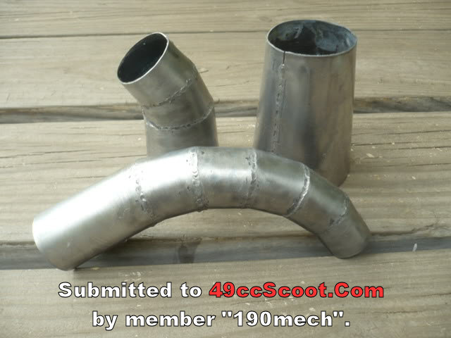 |
|
|
|
Post by 2strokd on Aug 6, 2014 9:18:11 GMT -5
After listening to you, reading up, and just learning more from being around em all i always look at a pipe from the flange back, in that order. It all starts there.. No tapered header=not such a good pipe.
|
|
|
|
Post by 190mech on Sept 11, 2014 9:15:55 GMT -5
For those who dont have access to a cone calculator online may use the old school method..The cone side view is drawn with a center line thru it,the C/L is extended till a straight edge laid across the top of the cone drawing intersects with the center line..(this could be many feet away with shallow taper headpipe cones!)..A straight edge can simply be a string pulled taught from the larger cone diameter..Once the pivot point is found,the above string can be attached there to scribe an arc at both ends of the cone,then the cone small od is multiplied by 3.14159 to get the circumference,string stretched at that point to mark the big radius,,and there it is!A hell of a lot harder than an online calculator!! 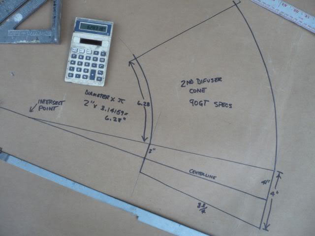 If you plan to use the "cut and flip" method to angle a cone,be sure to file the burrs and clean the chips from the inside of the chamber as the cylinder will get a load of steel chips when the pipe starts to work!!(ask me how I know!! ). For those who dont want to make a tapered headpipe,nice mandrel bends(good for the stinger too!) can be bought here; www.bassani.com/universal/tubing/A small 12" sheet metal roller is ideal for making pipes,but a steel rod clamped in a vice with much careful hammering can make do too; 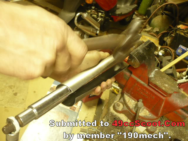 ViceGrips attached to both sides of the seam keeps the edges together to sew it up..With careful fitting,no filler rod is needed; 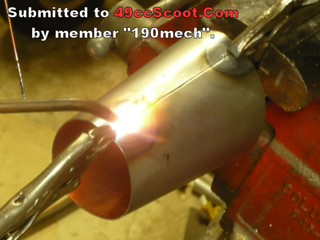 Do you just weld them up with a torch and a coat hangar? I could get into that! I braze copper pipe with 5% silver frequently in my line of work. I prefer an oxy-acetylene torch for pipe welding,TIG makes a nice pipe too..It'd be tough to MIG one as its too thin.. Ive been using CNC cut parts for the last few years,makes a much more accurate pipe.. Since Ive gone to CNC cutting of the sheet,common solid MIG wire is my filler rod with Oxy/Acetylene.. Here are a couple of vids of the process;   Another way to build pipes is hydroforming(YouTube has some vids)..2 flat sides are welded together and expanded with water pressure to get the desired shape.I wanted to try a 180 degree tapered headpipe for a quiet pipe in the works.I calculated the size and made a paper pattern,then cut out some sheet metal to match and welded it up after small flanges were made to ease welding; 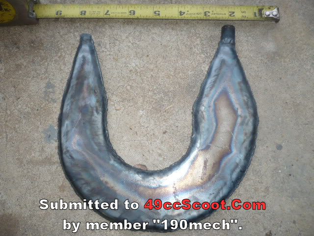 I used a pressure washer to provide the water pressure,it was a lot of work,but came out pretty well..As I read the forming causes the bends to be sharper as seen in this pic; 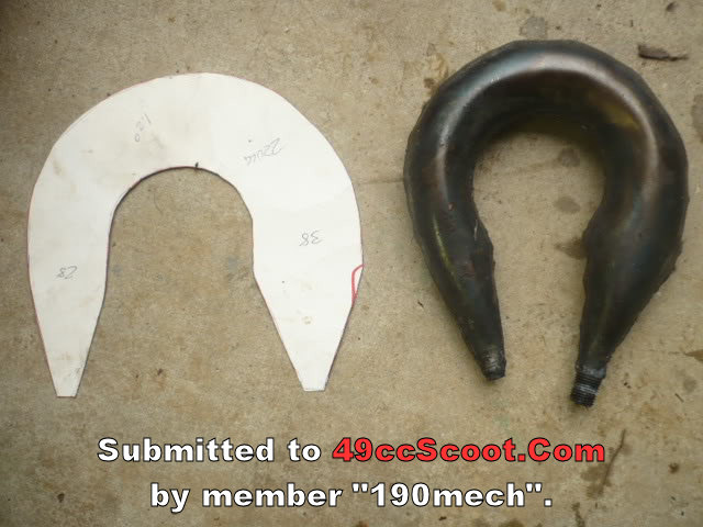 The pipe got its desired shape using the bend to shorten the over all package,its an experimental pipe that needs some more work to work really well; 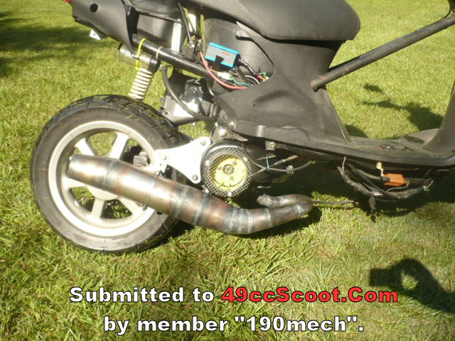 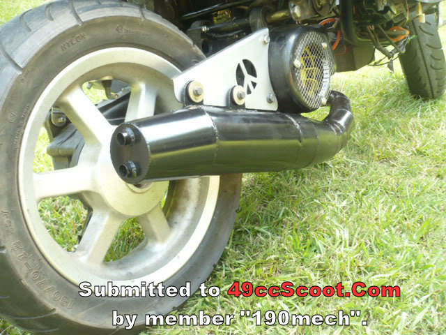 Here are some pics of "crude" pipe building techniques;Hand rolling with a supported steel rod,, 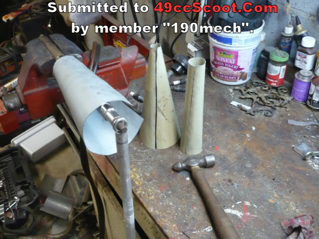 Cone clamped in a vice,welding with a coat hanger; 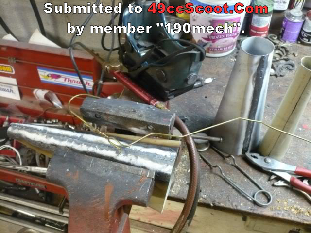 Headpipe/flange weld and 1st stage difuser tack up; 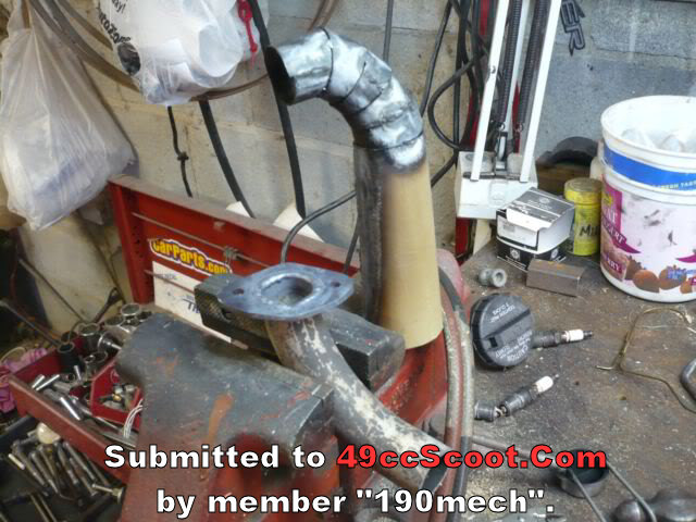 "cut and flip" fit up; 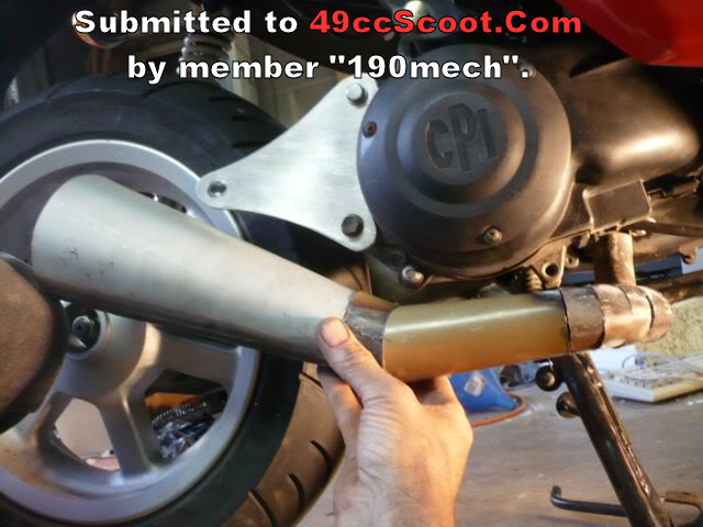 Body welded; 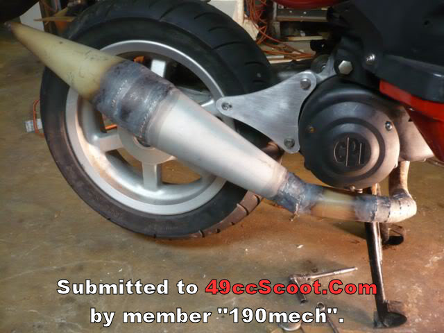 Silencer fabbed,note freeze plug end caps; 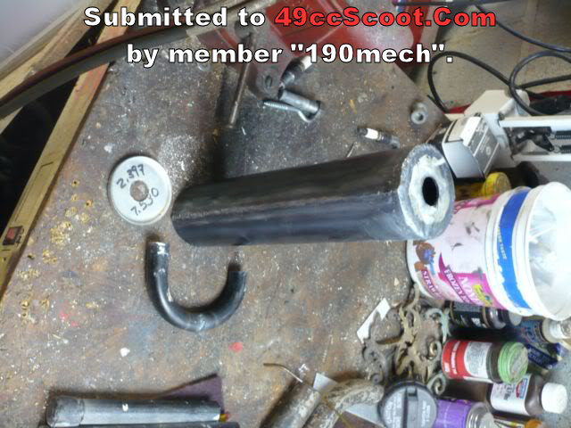 Sewed up; 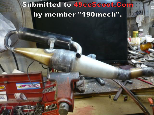 Rattle can ultra high speed silver!; 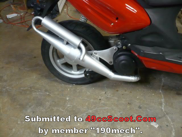 Hope this stuff gives y'all some ideas to get out in the garage and start cutting out,fitting and welding your own pipes! |
|
|
|
Post by 190mech on Sept 21, 2014 17:49:03 GMT -5
The most hated part of pipe building for me is SILENCERS!Lots of parts must be fabed and it takes waay too much time...As stated earlier,automotive freeze plugs make good end caps,the rear cam plug for an old Ford 390"FE" motor has the largest,easiest to find diameter(2 3/8 OD).The silencer core should be at least 3mm larger(or more) to not mess with the tuned length of the pipe..The core is made from perf sheet and hand formed around a suitable diameter steel rod,tack welded,then brazed to the fabed up end cap; 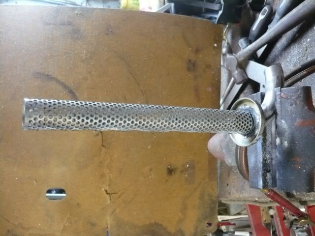 The outer tube is usually a rolled piece,or the proper size of aluminum tube,here are some pics of aluminum cans for an RD project; Parts fabed and test fitted;  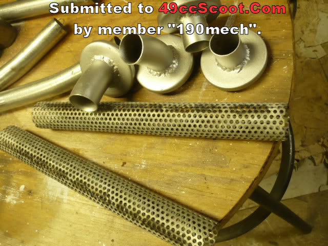 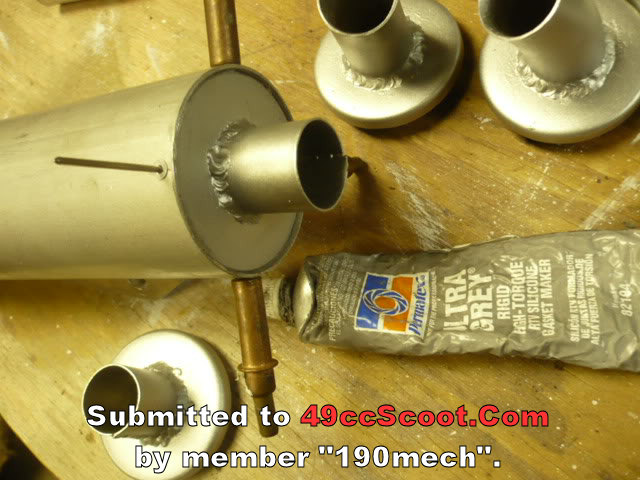 Sealed with Ultra Grey and pop riveted together; 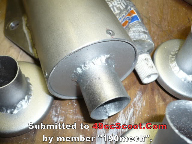 Ebay sound matting wrapped around the core and fed into the can; 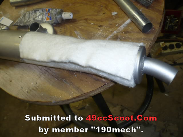 Ready to install; 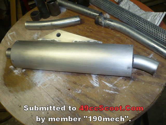 |
|
|
|
Post by 190mech on Oct 5, 2014 19:43:24 GMT -5
When calculating a pipe,the headpipe should be 30-33% of the pipe total length(from piston face to end of baffle cone) and the diffuser should be 64-68% total length..Thats what a world class 2T tuner stated on a road racing forum a while back..Gotta be true!!  I'm tired but that seems to add up to 100% how do you fit the rest of the pipe in? Lol Remember the measurement is from the piston face,so the diffuser length is including the headpipe and ex port length also.. |
|
|
|
Post by 190mech on Oct 6, 2014 4:02:09 GMT -5
Head pipe building/cut n flip,etc; Here is a pic guide to plotting a tapered head pipe, First a full size side view is drawn; 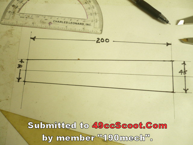 Then we pick a length for the first bend(say 30mm) and mark the centerline there.Place a protractor at that point and mark the 8 degree spot,then draw an intersecting line thru the 2 points; 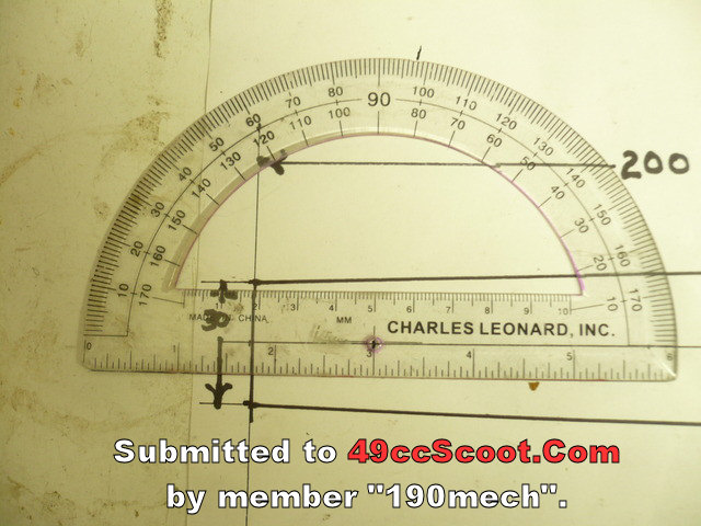 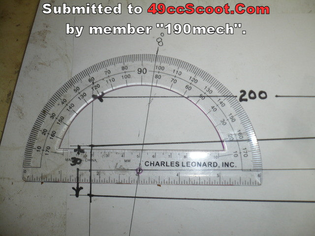 Thats our first cone layout,now to the second,,measure another 30mm down the centerline and mark it,protractor on that spot,mark 8 degrees in the Opposite Direction from the first like this; 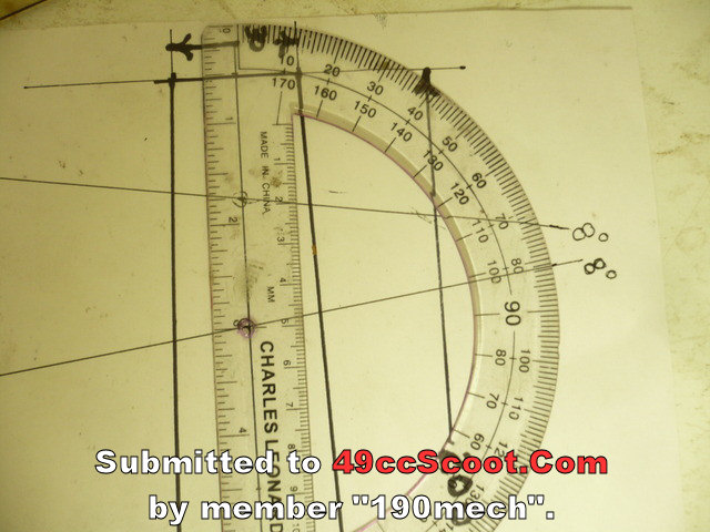 Then measure the length of the first angle cut; 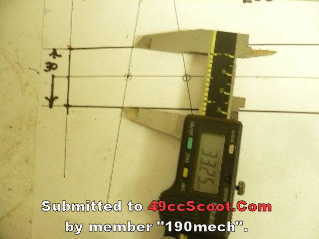 First cone is 30mm OD,0 degrees---30mm long---33.5mm OD,8 degrees; 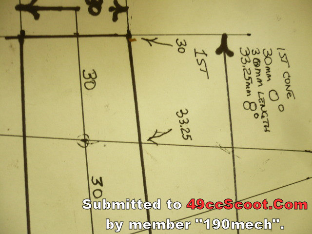 And we follow with the second cone like this; 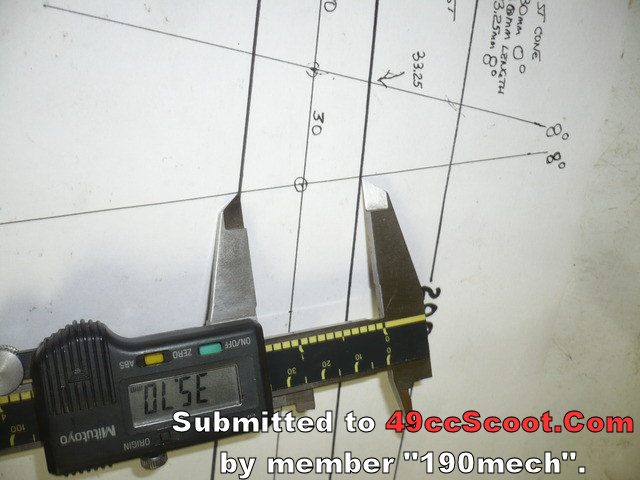 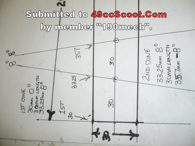 Second will measure 33.25mm,8 degree---30mm long---35.7mm,-8 degree(minus 8 degree) These numbers can be placed in the cone layout program to make perfect cutouts for a cun n flip head pipe.. Hope this helps! |
|
|
|
Post by 90GTVert on Oct 16, 2014 10:39:17 GMT -5
|
|
|
|
Post by oldgeek on Dec 24, 2014 20:23:56 GMT -5
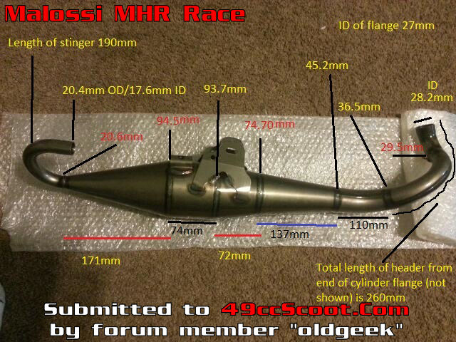 Head pipe is .8* 1st diffuser is 2.3* 2nd diffuser is 6.2* 3rd diffuser is 7.6* --spacer/belly--- baffle cone is 12.2* Total length 824 Head pipe 32% Head pipe/diffusers 70% Not a bad pipe!Headpipe and diffuser angles are a bit shallow making for a good pipe for lower to mid cylinder durations,Headpipe and headpipe/diffuser % are very close to spot on,it'll likely be good to 11,500-12,000 RPM's. Thats if there are no tree hugger baffles or screens inside!! |
|
|
|
Post by 90GTVert on Jan 7, 2015 22:28:15 GMT -5
I also just fished a piece of string through the pipe then measured the string. The string measured 835mm 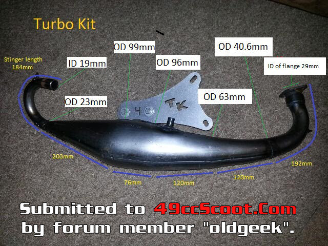 Waay Hot Rod pipe! Head pipe 1.7 degree 1st stage diffuser 5.4 degree 2nd stage diffuser 7.9 degree spacer/belly Baffle cone 10.7 degree total pipe length 611mm (stinger not included) head pipe 31% (30-32% ideal) Headpipe/diffuser 70.5% (64-68% ideal) The Yasuni C21 has a total length of 689mm,This one is only 611mm!Very high RPM set up needed..For a 90cc+ build a spacer in the head pipe,or belly would be needed to get the tuned length in the much lower range of 10.500 to 11,000 RPM.. OOPS!My mistake,I got 711 this time!!Sorry for missing that..Still a hot pipe though but will likely pull hard with the right 70cc cylinder set up... |
|
|
|
Post by 90GTVert on Mar 8, 2015 21:16:51 GMT -5
Here are my findings,Head pipe(first 2 sections)1.5 degrees-305mm long 1st stage diffuser 6.5 degree 2nd stage diffuser 7.2 degree Belly Baffle cone 12.3 degree This appears to be a 50-70cc pipe tuned for 11,000 max RPM's,around 185+ degrees exhaust duration,volume 3369 cc,should be a good street pipe for a mild cylinder.. Again,these calculations are for a hollow pipe with no internal baffles or screens... |
|
|
|
Post by 90GTVert on Mar 16, 2015 21:44:55 GMT -5
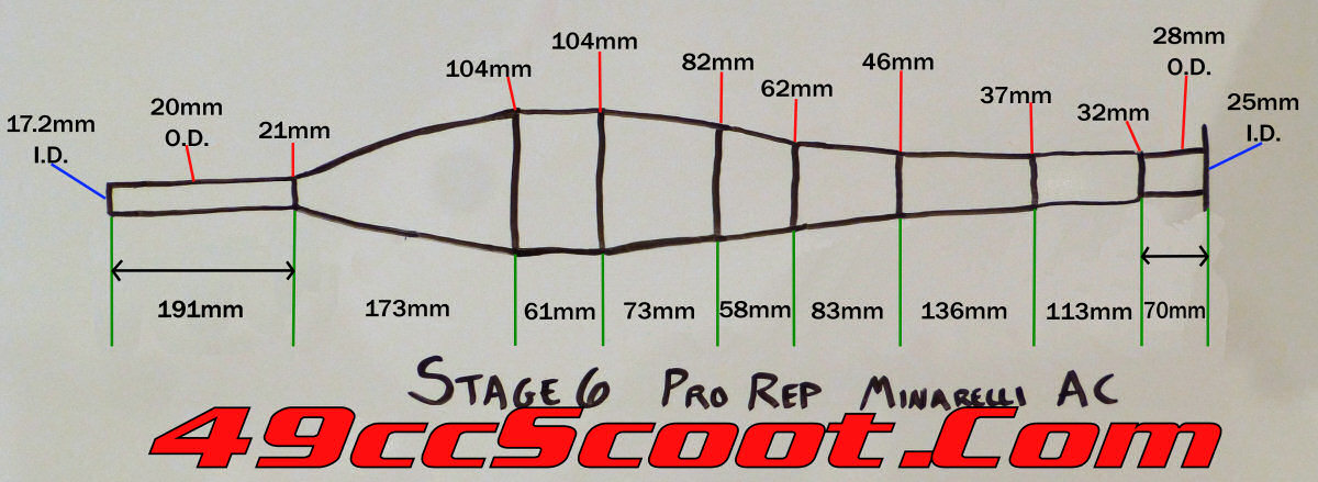 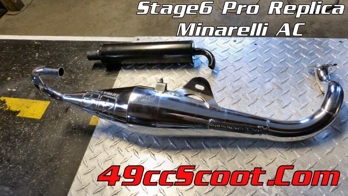 (50-70cc) |
|
|
|
Post by 90GTVert on Mar 18, 2015 18:46:31 GMT -5
Here we go, the dimensions of the Technigas RSII 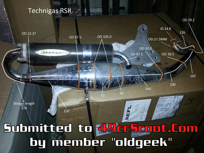 Has some strange angles,long and large for a 70,looks right in the ball park for a 90+ though!! 26-126-29.2 .73* 29.2-165-38.5 1.6* 38.5-100-53 4.15* 53-160-87.5 6.15* 87.5-50-105 10* 105-51-105 spacer 105-52-87.5 9.6* 87.5-150-23.7 12.25* total length 854(without stinger) headpipe 34%(ideal 30-32%) headpipe/diffuser 70.5%(ideal 64-68%) |
|
|
|
Post by 90GTVert on Apr 19, 2015 5:27:01 GMT -5
[  Think Ive seen this one before,,Long length makes it around 9400 rpm max,head pipe length is waay too long,diffuser % is long also due to the long headpipe,,Belly diameter is 50cc sized,ought to be around 100mm,tailpipe is borderline small,could cause high CHT..Sorry!Not a glowing review,just what I see in the dimensions..As always,this is calculated as a 'hollow pipe' with no baffles or screens(TechniGas is known for internal baffle cone screens..)..Shortening the headpipe and adding some belly length 'may' help it be a better pipe.. 50cc NextR Note I got one that says for 50cc on it even though the dimensions are exact the same as for the 100cc... So I just measured the pipe and before I started my Photoshop I quickly checked the pipe build thread and saw niz76 posted dimensions for a Next-R 100cc. I compared my data with his and I have the exact the same dimensions for my 50cc pipe. |
|
|
|
Post by 90GTVert on May 9, 2015 7:28:39 GMT -5
Two more pipe dimensions for ya'll. 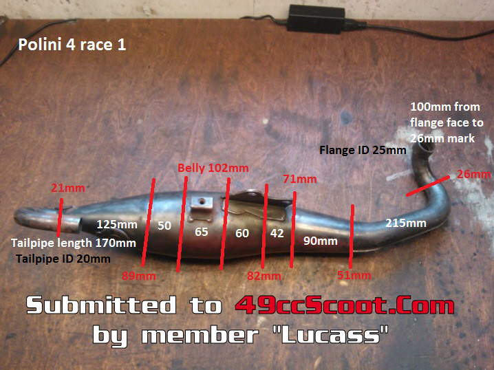 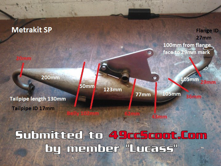 Re : Metrakit SP Total length equates to 11,700 RPM,headpipe % factor is off a good bit,from ideal,but it looks decent to the belly % ratio,,As always if there is any packing or screens inside,no accurate calculations can be made!! |
|