Using LED Turn Signals ( Relay / Flasher / Resistor Info )
Jan 8, 2016 9:07:24 GMT -5
190mech, spaz12, and 1 more like this
Post by 90GTVert on Jan 8, 2016 9:07:24 GMT -5
Many of us switch to LED turn signal bulbs or whole LED turn signal assemblies. They tend to last longer than incandescent bulbs, the use less power, they can be very bright, they react and illuminate more quickly, and they may improve appearance. Whatever the reason may be, it's not always as simple as just swapping out the bulbs or installing new lights.
LED lights put less of a load on the turn signal flasher relay, but it requires a certain amount of load to work properly. It may not function at all if there is a substantially smaller load from LEDs, or it may think a bulb is out and cause fast flashing (a.k.a. hyper-flashing). Please note, this should not be a problem if you're adding LED signals in addition to your stock signals.
Sometimes you'll get lucky and everything works as usual without additional modifications. If you've only replaced a pair of bulbs and not all four, the load from the remaining incandescent bulbs may be sufficient. Sometimes the standard indicator light in your instrument cluster will even provide enough load that turn signals continue to function properly. If you aren't so lucky and your blinkers no longer work as they should, there are ways to correct the issue.
The two popular methods are to replace the turn signal flasher relay with one that is intended for use with LEDs or to use resistors with the LED bulbs. Resistors, sometimes called load equalizers, are wired in with your existing turn signal wiring. There's a diagram of a typical installation below, using what seems to be the most common resistor (50W, 6Ω), and some wiring info. They are intended to make the LED mimic the load of a standard bulb so they stock turn signal flasher won't know the difference. You may have to install multiple resistors to get your lights working properly. Resistors waste energy in the form of heat. It may not be a lot of energy, but if you've upgraded to reduce power use, why install something that wastes it? Since the energy is converted to heat, resistors may get hot. If you aren't using your turn signals often, it may never be an issue, but you should always mount them to a metal surface and keep them away from anything flammable or that may melt.
For those reasons, I find it easier to replace the turn signal flasher relay with one that's not load dependent and intended for use with LED bulbs. It's a relatively easy swap since you're only replacing one part in one location, and it shouldn't emit much heat or use extra energy like resistors. The biggest problem with replacing the relay is finding one that actually works, and that's not really difficult. When I first bought LED relays, I bought a couple that claimed to be good for use with LEDs. They were a standard 2 prong design that you can find in most auto parts stores. Even though they were said to work with LED signals, they did not function properly in my experience. Since then, I use 2 prong flashers with an additional wire coming out of them. These have never failed me. You may even be able to find different designs that are plug and play with your scooter, but I've only used units as shown below.
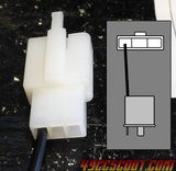
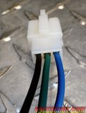
The two most common connections that I've seen for small scooters, especially Chinese, are the typical 2 prong L shaped socket and the 3 wire Hitachi/MTW style connector (the same style as most other 3 wire connections on a Chinese scooter).
If you have the 2 prong L shaped style, adding an LED flasher like the one shown above is simple. All you have to do is plug the new turn signal flasher relay in and then run the wire coming out of it to a ground. You can tap into a ground on the harness, the negative battery terminal, or even secure it with the supplied connector or a ring terminal to the frame for a ground. That's all there is to it.
If you have a flasher that uses a Hitachi/MTW connector, a bit more effort is involved, but it's not difficult. I just hooked up an LED flasher in place of this kind of unit, so I'll show you how I installed it below.


