Post by 90GTVert on Apr 22, 2011 8:41:23 GMT -5
This Koso tachometer and cylinder heat temperature (CHT) gauge is a very nice piece, and comes complete with the gauge, instructions, wiring, a temperature sender for liquid cooled engines, and mounting hardware.
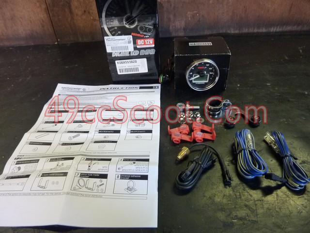
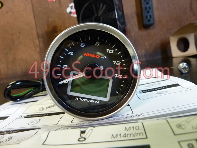

Here are the instructions that come with it.


*Disconnect the battery negative terminal before doing any electrical work.*
I started out by choosing a spot, and mounting the gauge. When choosing a mounting location, make sure all wires will reach. Choose an area that is easily in view so you don't have to look away from what's ahead of you to view it. I chose what is probably the most common mounting location, on the handlebars.
The gauge comes with a handlebar clamp and bracket that makes mounting this way a snap.

Put the clamp around the handlebars.
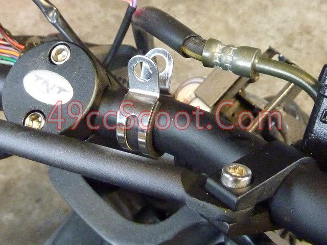
Install the mount on the studs at the rear of the tach using the supplied hardware.
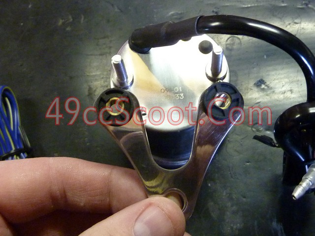
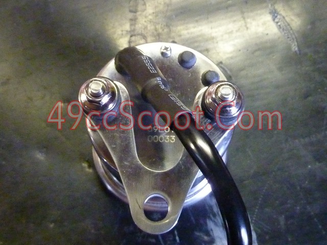
Install the mount to the handlebar clamp, but don't tighten it all the way yet. Sit on the scooter in your riding position and move the tach to whatever angle allows for the easiest viewing. Then tighten it.
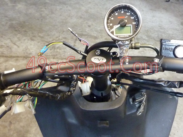
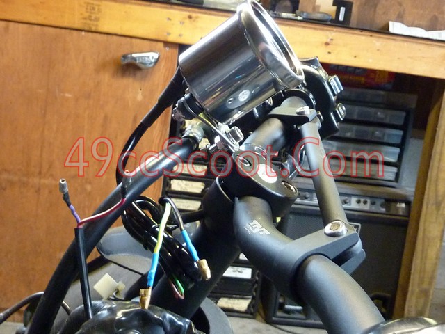
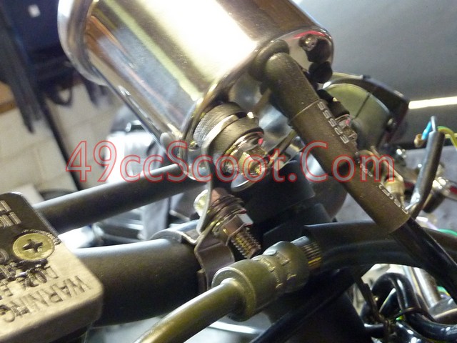
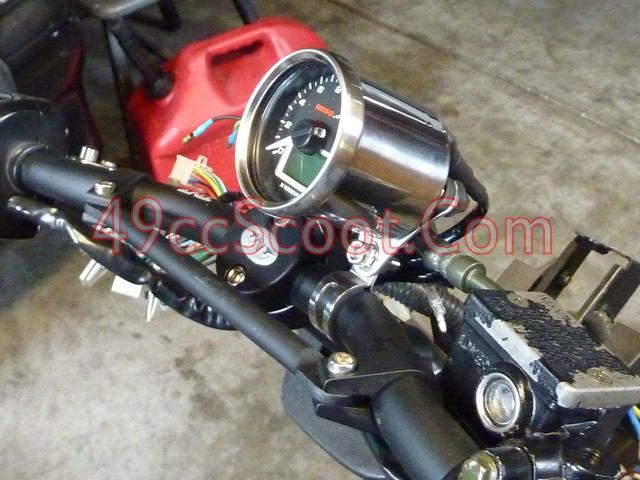
With the mounting covered, you can move on to the wiring. I began with the power and ground connections. You should have one red, one black, and one brown stripped wires. There is another brown wire, which should have a connector on the end of it. It's for the tach signal, which we'll get to later.
Red : 12V +
Connect to the positive terminal of the battery. Constant power.
Brown : Ignition Switched 12V +
This needs to be connected to a 12V + power source that is switched on and off by the ignition switch (key). This tells the gauge when to power up.
Black : 12V - Ground
Connect to the engine, a good frame ground, or battery ground.
Since I had removed my stock gauge cluster, I had a leftover connector that used to power it. I suspected all of the power sources I needed were right in that harness. Using a multimeter (a test light or volt meter would work fine for this purpose) I checked the wires and noted which had constant 12V+, 12V-, and ignition switched 12V+.
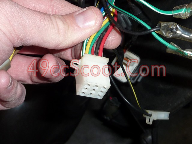
I placed the stripped wires in the spots I checked that should work, reconnected the battery, and then turned the ignition switch on. The tach should come on at this point. If not, something's not wired properly. Disconnect the battery again once you know the wiring is correct.
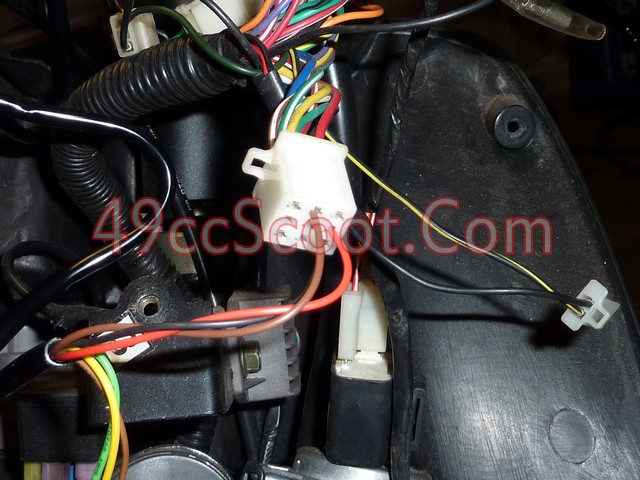
I had an old wiring harness lying around. Luckily most scooters use a lot of generic connectors, so I found one that worked with my stock gauge cluster connector. If you don't have a connector to fit, you could just use the wires that were going into the stock connector. Of course you also have the option of running all new wires to the appropriate power sources. I like this way because it's a quick disconnect should I ever need to remove the tach or harness.
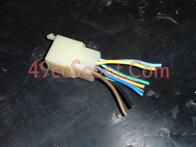
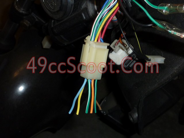
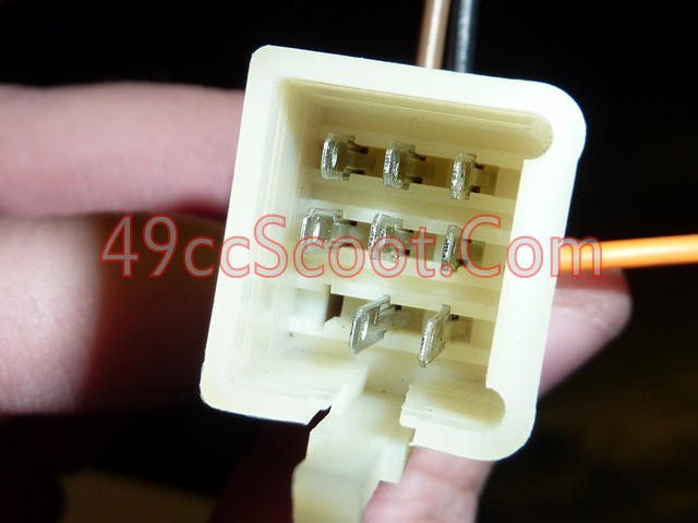
Once I knew which 3 wires I'd need to match up with the correct wires in the scoot's harness, I removed the rest of the wires from the plug. If you look into the connector, as in the 2nd pic below, you can see a little tab on each prong inside. Pressing the tab down with a small screwdriver will allow you to remove the wire from the connector.
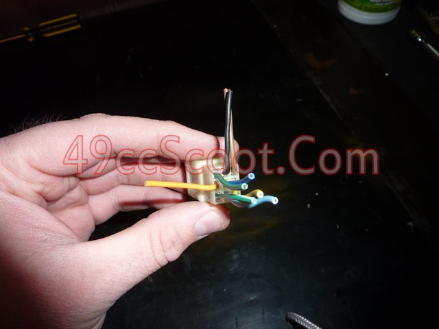
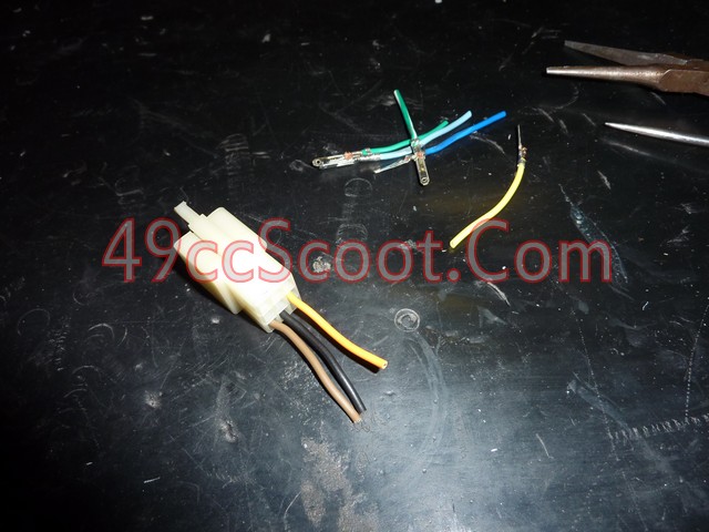
Then I soldered the connector to the appropriate wires to the tach.
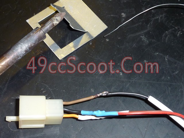
Now everything is setup for quick disconnect.
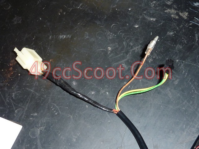
I plugged in the harness and reconnected the battery long enough to verify all of my connections were good.
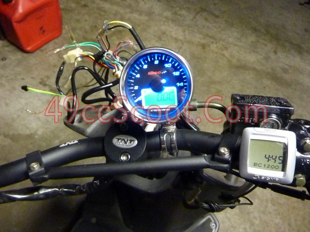
I moved on to the tach input signal next. This is the brown wire from the gauge that has a male bullet connector on the end of it. Koso supplies two different wires to give you different options for connecting to a trigger signal.
One is a wire with a female bullet connector at one end to connect to the gauge and no connector on the other. This is intended to be wrapped around the spark plug wire to obtain a signal.
The other wire has a female bullet connector at one end to connect to the gauge. The other end has male and female quick disconnect terminals as shown below to allow connection directly to the ignition coil.
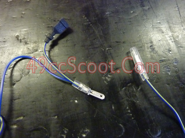
Some users have reported problems with the engine breaking up when the wire is connected directly to the coil. I used the direct to coil method without a problem.
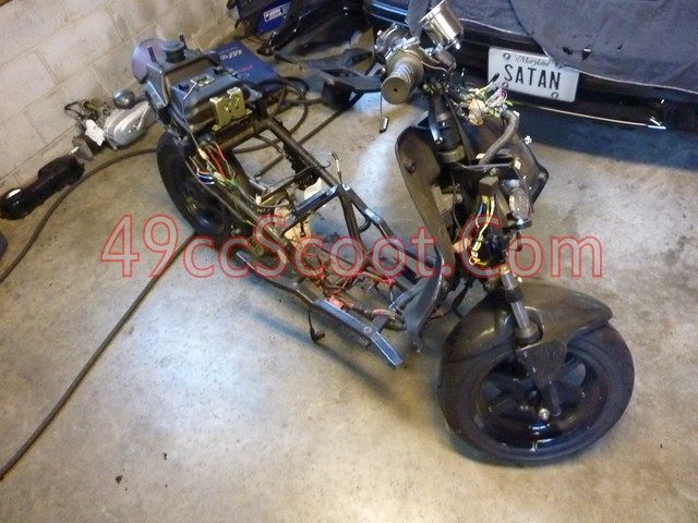
If you haven't done it already for the method you chose to wire up the power connections, now you'll need to strip the body panels off of your scoot so you can start running wires. I suggest also connecting the temperature sender wire and running any wires that you need together, rather than doing them all separately.
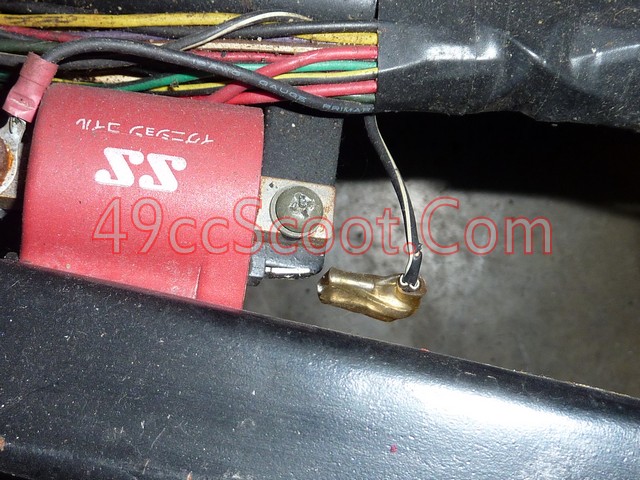
Once your tach signal wire is at the coil, disconnect the coil's positive wire, usually black with a white stripe.
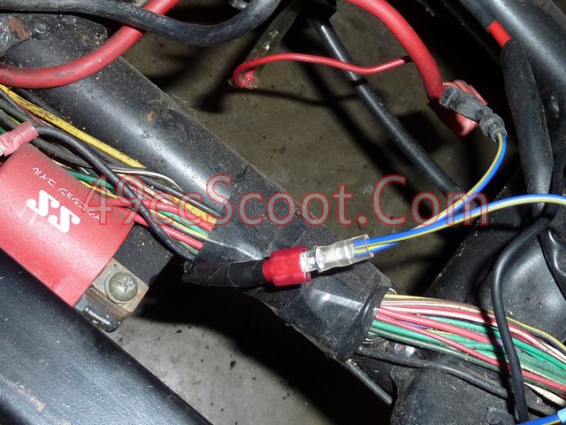
Connect the male connector from the tach to the female connector that was on the coil. If your connector is in bad shape, as mine was, now is a good time to replace it and ensure reliable spark.
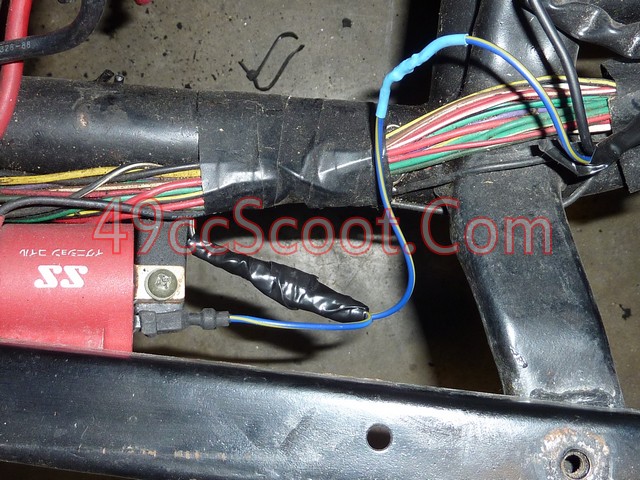
Then connect the female connector from the gauge to the coil's terminal. Once it's all secured, that will conclude the tach wiring. You may wish to test at this point to be sure it works. You may notice my signal wire has been soldered together. It was very long, so rather than bunching up a lot of wire, I cut it down to size and soldered it back together.
Now you can move on to the temperature sensor. You should already have ran the wiring mostly across the scooter if you followed my instructions above, so all that's left is to run the wire the rest of the way to the engine and to install the sensor.
The sensor supplied with the kit is intended for liquid cooled scooters. If that's what you have, you should be able to just plug it in. If you have an air cooled scooter you're going to need to do some work. This is for 2Ts, not sure where to install it on a 4T, but this might give you some ideas.
I drilled a hole through 2 fins on my cylinder head. That is enough to allow the sender to mount right up against the first fin. Then I tapped both holes with the appropriate thread for the sender, which is slipping my mind at the moment. I wanna say it's NPT, but I can't recall for certain and I can't seem to find my notes from the install.
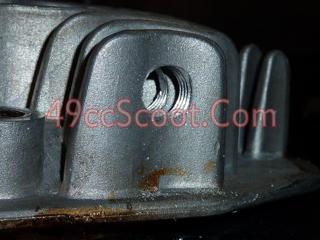
Once the holes are drilled and tapped, screw the sender in. Be careful not to overtighten it and break off a cooling fin.
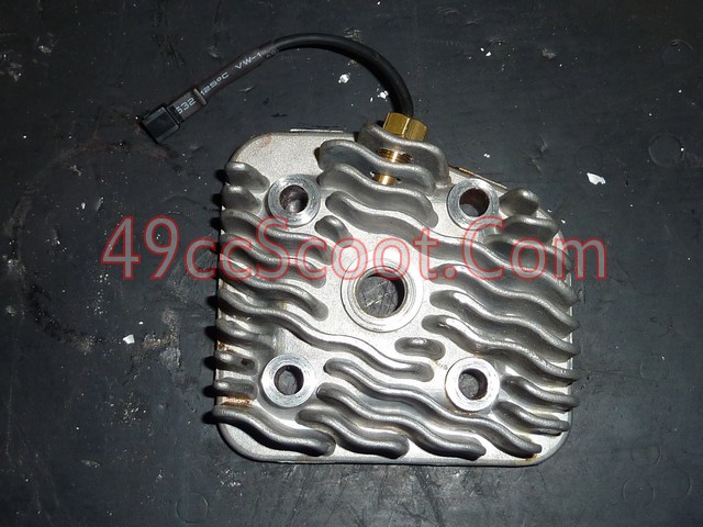
Connect the sender to the wire from the tach.
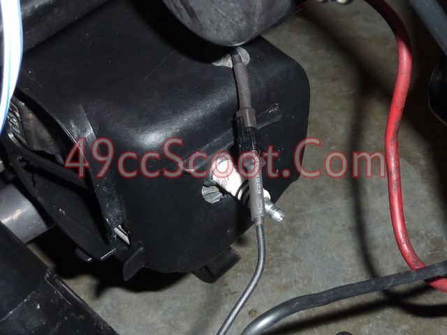
Now you just need to test everything for proper operation, tie up any loose ends with your wiring, and get your scooter back together.


Here are the instructions that come with it.


*Disconnect the battery negative terminal before doing any electrical work.*
I started out by choosing a spot, and mounting the gauge. When choosing a mounting location, make sure all wires will reach. Choose an area that is easily in view so you don't have to look away from what's ahead of you to view it. I chose what is probably the most common mounting location, on the handlebars.
The gauge comes with a handlebar clamp and bracket that makes mounting this way a snap.

Put the clamp around the handlebars.

Install the mount on the studs at the rear of the tach using the supplied hardware.


Install the mount to the handlebar clamp, but don't tighten it all the way yet. Sit on the scooter in your riding position and move the tach to whatever angle allows for the easiest viewing. Then tighten it.


With the mounting covered, you can move on to the wiring. I began with the power and ground connections. You should have one red, one black, and one brown stripped wires. There is another brown wire, which should have a connector on the end of it. It's for the tach signal, which we'll get to later.
Red : 12V +
Connect to the positive terminal of the battery. Constant power.
Brown : Ignition Switched 12V +
This needs to be connected to a 12V + power source that is switched on and off by the ignition switch (key). This tells the gauge when to power up.
Black : 12V - Ground
Connect to the engine, a good frame ground, or battery ground.
Since I had removed my stock gauge cluster, I had a leftover connector that used to power it. I suspected all of the power sources I needed were right in that harness. Using a multimeter (a test light or volt meter would work fine for this purpose) I checked the wires and noted which had constant 12V+, 12V-, and ignition switched 12V+.

I placed the stripped wires in the spots I checked that should work, reconnected the battery, and then turned the ignition switch on. The tach should come on at this point. If not, something's not wired properly. Disconnect the battery again once you know the wiring is correct.

I had an old wiring harness lying around. Luckily most scooters use a lot of generic connectors, so I found one that worked with my stock gauge cluster connector. If you don't have a connector to fit, you could just use the wires that were going into the stock connector. Of course you also have the option of running all new wires to the appropriate power sources. I like this way because it's a quick disconnect should I ever need to remove the tach or harness.


Once I knew which 3 wires I'd need to match up with the correct wires in the scoot's harness, I removed the rest of the wires from the plug. If you look into the connector, as in the 2nd pic below, you can see a little tab on each prong inside. Pressing the tab down with a small screwdriver will allow you to remove the wire from the connector.


Then I soldered the connector to the appropriate wires to the tach.

Now everything is setup for quick disconnect.

I plugged in the harness and reconnected the battery long enough to verify all of my connections were good.

I moved on to the tach input signal next. This is the brown wire from the gauge that has a male bullet connector on the end of it. Koso supplies two different wires to give you different options for connecting to a trigger signal.
One is a wire with a female bullet connector at one end to connect to the gauge and no connector on the other. This is intended to be wrapped around the spark plug wire to obtain a signal.
The other wire has a female bullet connector at one end to connect to the gauge. The other end has male and female quick disconnect terminals as shown below to allow connection directly to the ignition coil.

Some users have reported problems with the engine breaking up when the wire is connected directly to the coil. I used the direct to coil method without a problem.
If you haven't done it already for the method you chose to wire up the power connections, now you'll need to strip the body panels off of your scoot so you can start running wires. I suggest also connecting the temperature sender wire and running any wires that you need together, rather than doing them all separately.

Once your tach signal wire is at the coil, disconnect the coil's positive wire, usually black with a white stripe.

Connect the male connector from the tach to the female connector that was on the coil. If your connector is in bad shape, as mine was, now is a good time to replace it and ensure reliable spark.

Then connect the female connector from the gauge to the coil's terminal. Once it's all secured, that will conclude the tach wiring. You may wish to test at this point to be sure it works. You may notice my signal wire has been soldered together. It was very long, so rather than bunching up a lot of wire, I cut it down to size and soldered it back together.

Now you can move on to the temperature sensor. You should already have ran the wiring mostly across the scooter if you followed my instructions above, so all that's left is to run the wire the rest of the way to the engine and to install the sensor.
The sensor supplied with the kit is intended for liquid cooled scooters. If that's what you have, you should be able to just plug it in. If you have an air cooled scooter you're going to need to do some work. This is for 2Ts, not sure where to install it on a 4T, but this might give you some ideas.
I drilled a hole through 2 fins on my cylinder head. That is enough to allow the sender to mount right up against the first fin. Then I tapped both holes with the appropriate thread for the sender, which is slipping my mind at the moment. I wanna say it's NPT, but I can't recall for certain and I can't seem to find my notes from the install.

Once the holes are drilled and tapped, screw the sender in. Be careful not to overtighten it and break off a cooling fin.

Connect the sender to the wire from the tach.

Now you just need to test everything for proper operation, tie up any loose ends with your wiring, and get your scooter back together.

