PT100 temp sensor build up(14mm plug)
May 30, 2017 23:46:07 GMT -5
90GTVert, 190mech, and 1 more like this
Post by gsx600racer on May 30, 2017 23:46:07 GMT -5
This is for those that have purchased one of those off brand temp sensors that come with the NTP sensor that max out at 300°. You will need the PT100 thermal sensor to measure higher temps.
Sensor www.ebay.com/itm/152379525990
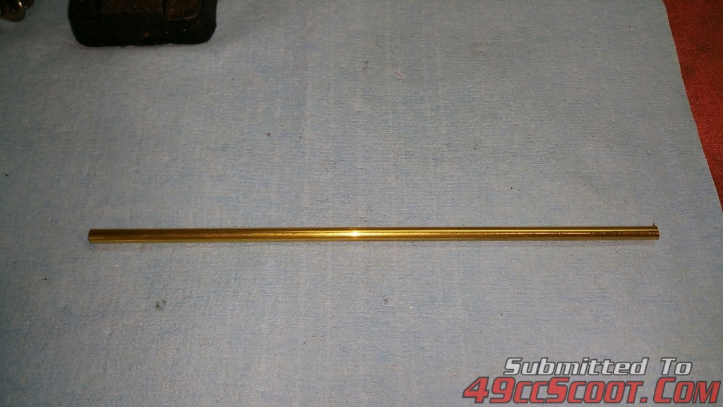
K&S 8129 3/16 x. 014 x 12" brass tubing (hobby store or web)
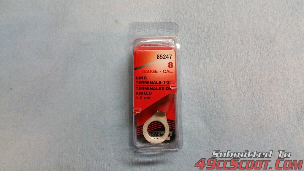
Dorman 85247 1/2" 8-Gauge Ring Terminal (auto parts store)

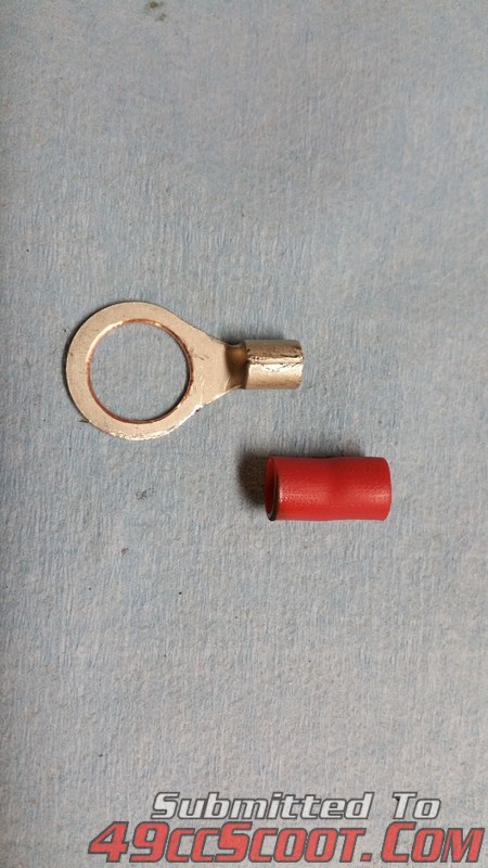
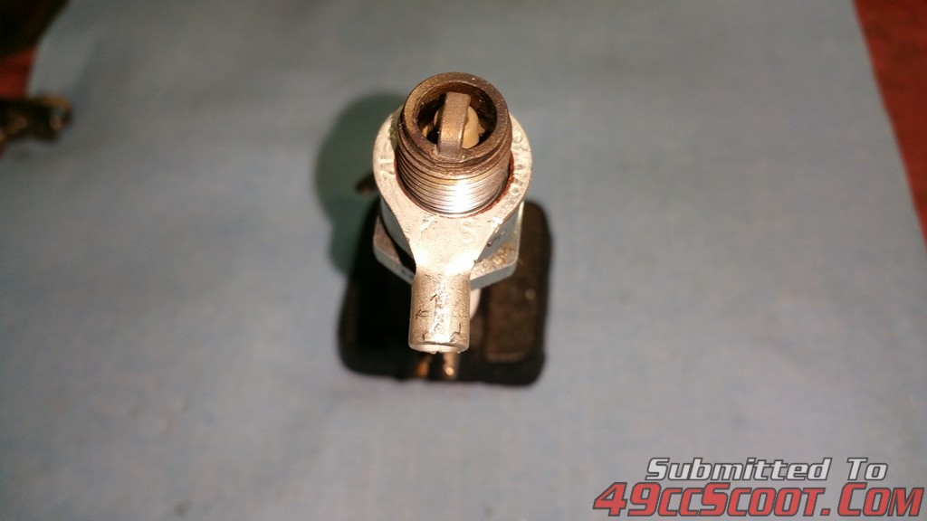
I first mod the ring terminal so it will fit over a 14mm spark plug(drill out). I also remove the insulator(red) and bend the crimp area 90° or so.
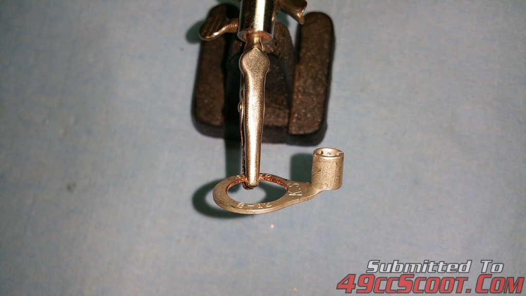
I cut a piece of brass tubing 1/8"-3/16" longer than the sensor(longer is better, reason later) and make sure it fits in the terminal crimp area. You may have to drill it open, don't force it in or the sensor will not fit. Then solder both pieces together. I found solder @ home depot that has a melting temp of 575°. You could also use a dab of JB weld.
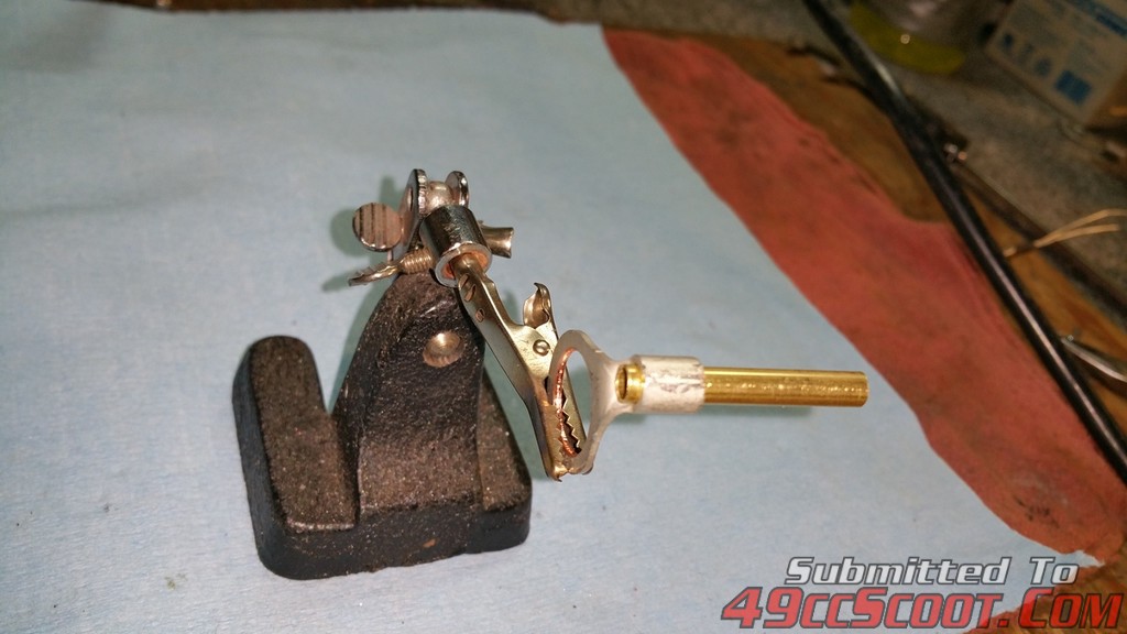
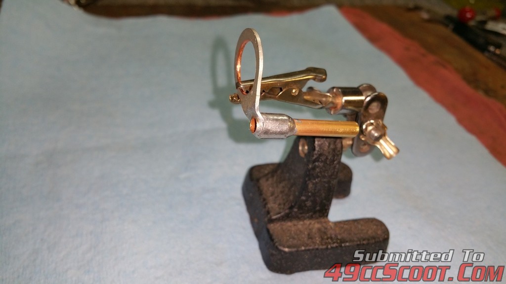
Next is the assembly of the sensor. You will need to scrap the label off the sensor, it will not fit in the tube or it will get stuck before its fully inserted.
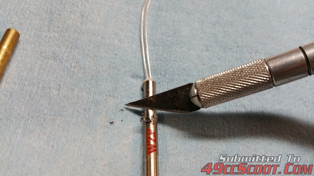
The next steps are crucial for success. Take your time. The leads on the sensor are not that forgiving, and you need to use extra care. I cut a couple pieces of heat shrink tubing, and use them for strain relief. 3/4 to 1" long. Shrink them on.
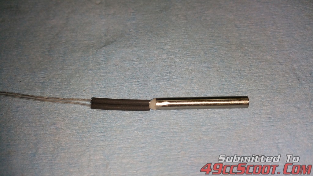
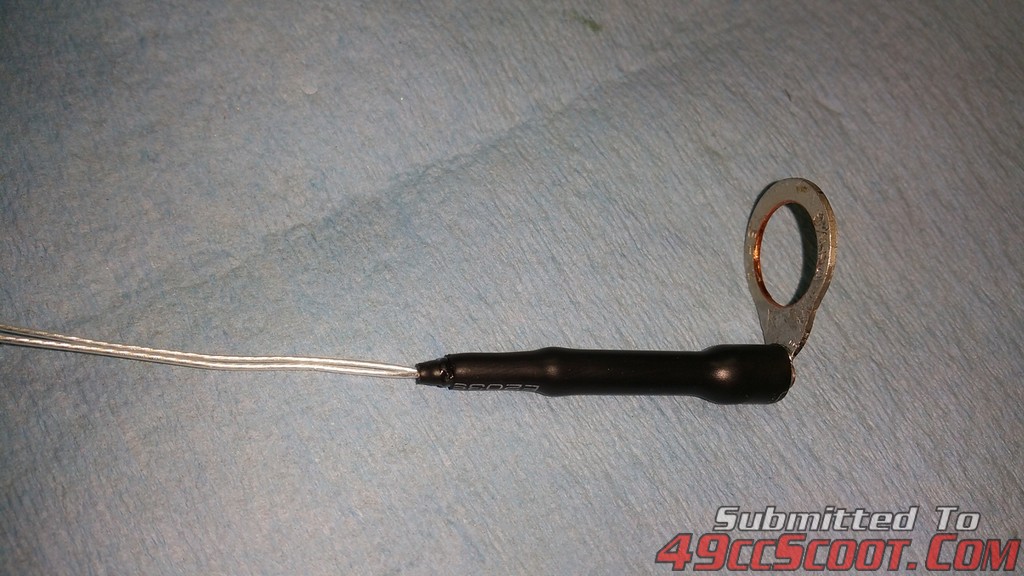
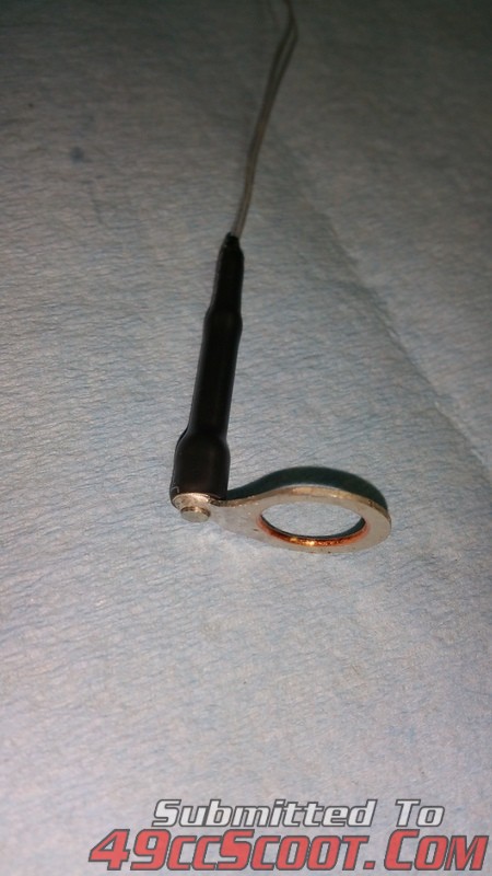
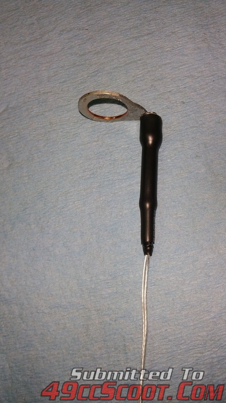
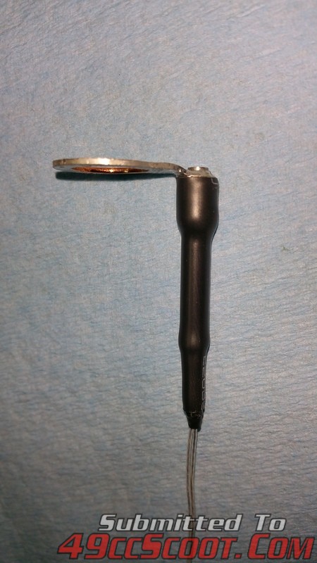
Insert the sensor assembly into the brass tubing. I let stick out a 1/16" on the bottom(closest to the spark plug opening) Note the position of the leads, you want them to easily bend towards or away from the plug hole.(see picture of orientation)
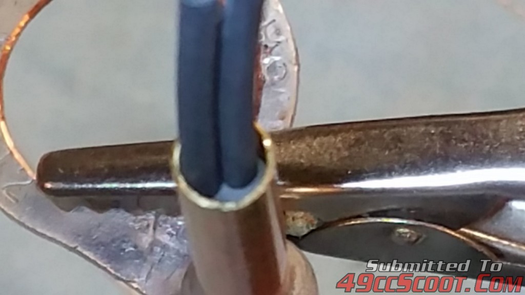
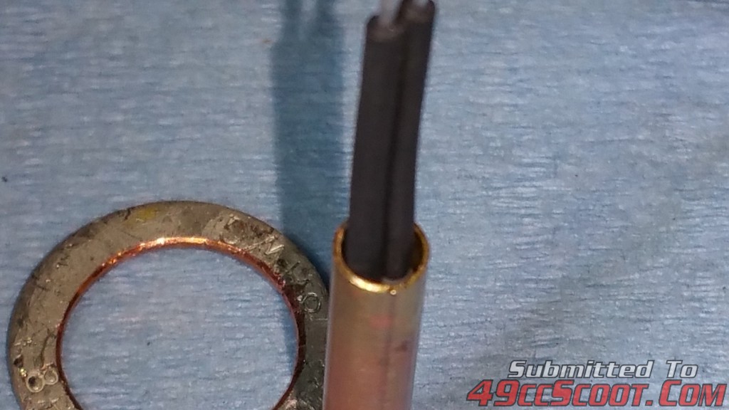
You want a small pocket where the leads exit's the brass tube. I use regular JB weld(not kwik) to fill this pocket and make a small fillet. I use a heat gun(sparingly) get the epoxy to flow easier to fill the pocket. The more heat you use will take away from the cure time and it will set up faster before you have things the way you like.
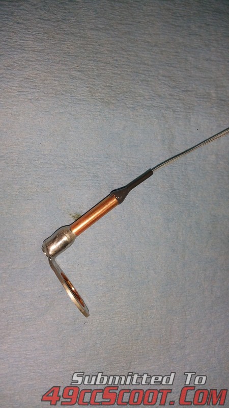
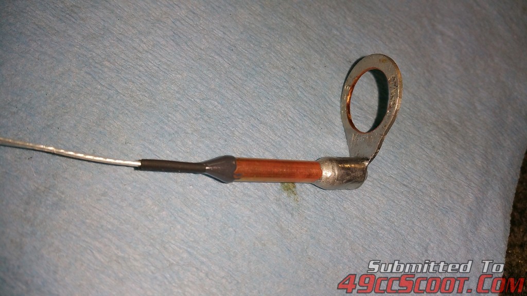
Once the epoxy has cured, I build up where the leads exit the brass tube with more heat shrink and take one large piece and cover the whole brass tube.
Now the fun stuff(technical)
I suggest keeping the leads as long as possible. Soldering iron/gun heat kills these sensors. The shorter the leads, the heat will travel down the wire and cook the guts inside and then they will no longer be accurate.(I know, I'v destroyed several)
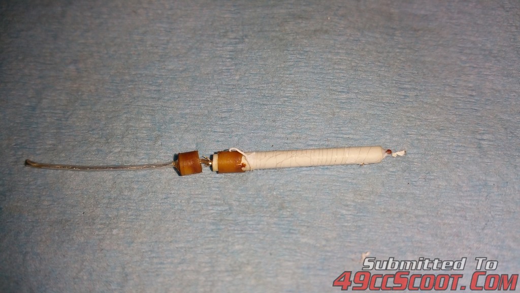
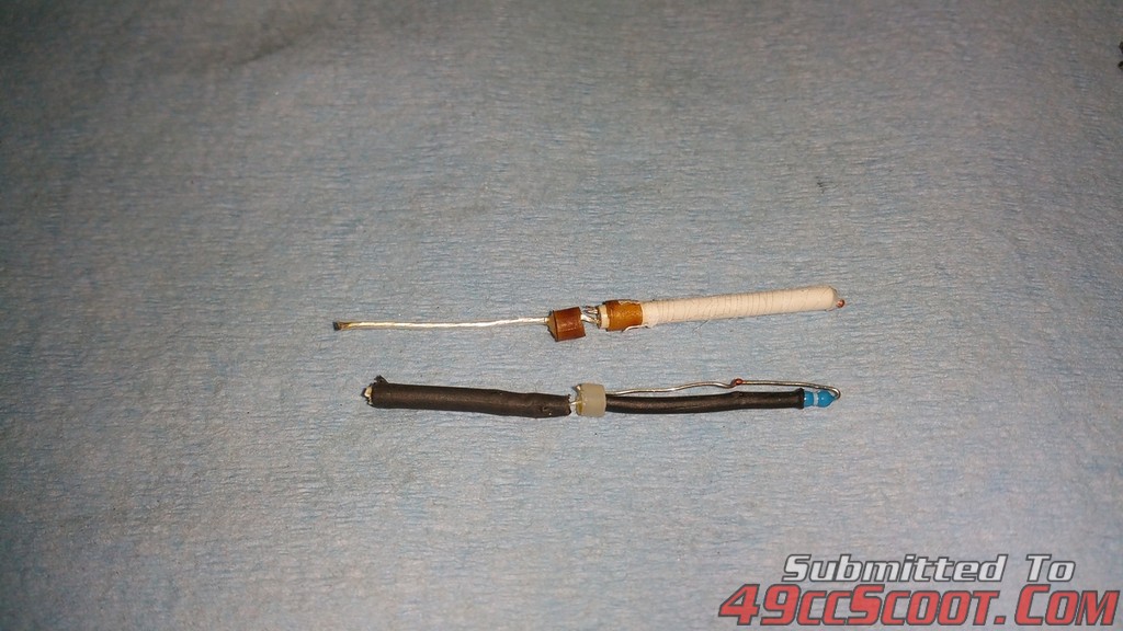
Here is what they look like inside, there are 2 types.(resistor(blue) and platinum coil(white)) The resistor IMO suck, super sensitive to solder iron/gun heat. Platinum are my preferred choice. You can faintly see the platinum wire coiled on the ceramic core(they easily broke when I took it apart)
Choice of wire: You really want to match the gauge as close as possible, and keep your run length "just enough" with a little for strain relief. Using speaker wire or something heavier will take away from the accuracy of the sensor.(wire impedance plays a major factor) I really would like to have used the same silicone wire that Trail Tech uses for their temp sensors but that stuff is expensive unless you buy the 72" extension and cut it up.
Enjoy and happy building.
Sensor www.ebay.com/itm/152379525990
K&S 8129 3/16 x. 014 x 12" brass tubing (hobby store or web)
Dorman 85247 1/2" 8-Gauge Ring Terminal (auto parts store)


I first mod the ring terminal so it will fit over a 14mm spark plug(drill out). I also remove the insulator(red) and bend the crimp area 90° or so.


I cut a piece of brass tubing 1/8"-3/16" longer than the sensor(longer is better, reason later) and make sure it fits in the terminal crimp area. You may have to drill it open, don't force it in or the sensor will not fit. Then solder both pieces together. I found solder @ home depot that has a melting temp of 575°. You could also use a dab of JB weld.


Next is the assembly of the sensor. You will need to scrap the label off the sensor, it will not fit in the tube or it will get stuck before its fully inserted.

The next steps are crucial for success. Take your time. The leads on the sensor are not that forgiving, and you need to use extra care. I cut a couple pieces of heat shrink tubing, and use them for strain relief. 3/4 to 1" long. Shrink them on.

Insert the sensor assembly into the brass tubing. I let stick out a 1/16" on the bottom(closest to the spark plug opening) Note the position of the leads, you want them to easily bend towards or away from the plug hole.(see picture of orientation)


You want a small pocket where the leads exit's the brass tube. I use regular JB weld(not kwik) to fill this pocket and make a small fillet. I use a heat gun(sparingly) get the epoxy to flow easier to fill the pocket. The more heat you use will take away from the cure time and it will set up faster before you have things the way you like.


Once the epoxy has cured, I build up where the leads exit the brass tube with more heat shrink and take one large piece and cover the whole brass tube.


Now the fun stuff(technical)
I suggest keeping the leads as long as possible. Soldering iron/gun heat kills these sensors. The shorter the leads, the heat will travel down the wire and cook the guts inside and then they will no longer be accurate.(I know, I'v destroyed several)
Here is what they look like inside, there are 2 types.(resistor(blue) and platinum coil(white)) The resistor IMO suck, super sensitive to solder iron/gun heat. Platinum are my preferred choice. You can faintly see the platinum wire coiled on the ceramic core(they easily broke when I took it apart)


Choice of wire: You really want to match the gauge as close as possible, and keep your run length "just enough" with a little for strain relief. Using speaker wire or something heavier will take away from the accuracy of the sensor.(wire impedance plays a major factor) I really would like to have used the same silicone wire that Trail Tech uses for their temp sensors but that stuff is expensive unless you buy the 72" extension and cut it up.
Enjoy and happy building.

