|
|
Post by marshinman on Jun 2, 2011 18:23:04 GMT -5
A short while back I had messaged Brent and within our conversation he showed some interest to being able to add lighting to his Sigma Digital Speedometer. So I told him give me a minute and I will figure it out. Being that I tinker in electronics I sat down and figured out what was needed in the way of a circuit to make two LED's light without burning them out on the 12v system the scooter has. Here is what I came up with and tested. First you will need two WHITE led's why white you may ask, because they for one will accept the highest voltage/current and two if want to see something you would not want to use red. Second you will need a 22k resistor (Red/Red/Orange color band). Third wire the LED's in series with the resistor. You can wire them into your head light switch so them come at the same time as your head lights. While they do work and do look fairly nice I found a way to make them light up more and give them a little more style. Using a piece of aquarium air line that you can pick up at your pet store and some black tape or heat shrink tubing. Now I only used a 4" piece of air line any longer than that any the effect is not quite the same. Place one LED into each end of the air line, use black tape to wrap around the LED where it is inserted or you can use black heat shrink tubing. This will allow the LED's to shine against each other and create the effect of a Florescent light. This small circuit will not drain your battery enough to ever notice it. I have one hooked up to a 12v 14ah battery right now and it has been running for 3 days and the battery will start my scooter. Here is a rough, very rough drawing of the circuit. 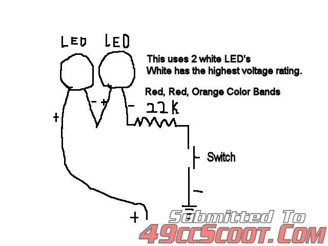 |
|
|
|
Post by 90GTVert on Jun 14, 2011 21:15:59 GMT -5
I was screwing around with this a little. I started out with a 4" tube and just zip tied it on to see how it worked. 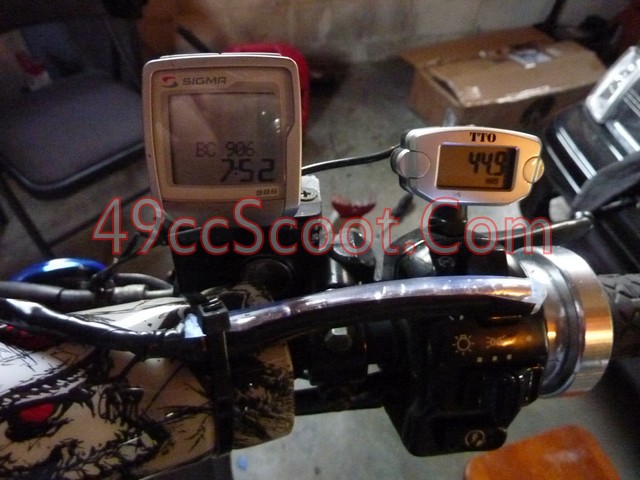 It didn't really work well as tied, but moving it a little made the gauge easy to read. 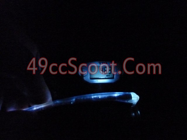 The tubing isn't really lighting up much and I can't light both gauges, so I just made a small version to mount by the tach. Started by hot gluing an LED in each end of 1/4" clear hose. 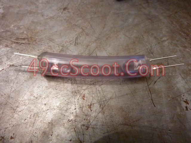 Wired it as marshin said. 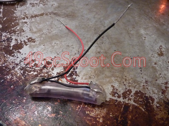 Added on some wiring and the resistor missing in the above photo. Made a bracket. Used some vacuum caps to spruce up the ends. 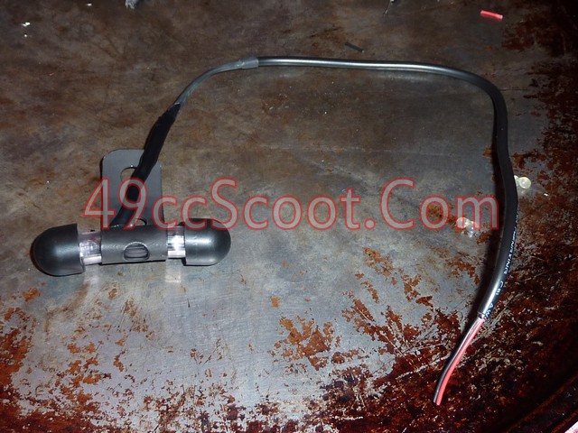 It works, but it would need to be higher up to be most effective. 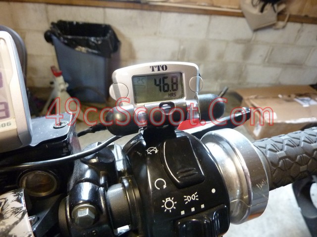 |
|
|
|
Post by 90GTVert on Jun 17, 2011 5:41:15 GMT -5
I wa playing around with this more. You could light a gauge with 1 LED pretty well if it's setup right. I put 4 LEDs in a tube and drilled in so they were facing toward the gauge instead of toward each other. 2 on each end since my bracket covers the center. 1 of the LEDs was out, so I had 1 on 1 end. I covered the side with 2 and moved the 1 LED around so it was aimed at the gauge the best and it easily lit the face up. These things do more of a beam than I though. The only bad thing is they need to be a little far back to work that way. They're actually quite bright though when aimed rather than just shining down a tube at each other as I had them.
|
|
|
|
Post by 90GTVert on Jun 17, 2011 13:24:19 GMT -5
Here we go again... Made up two "spotlights". 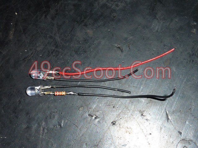 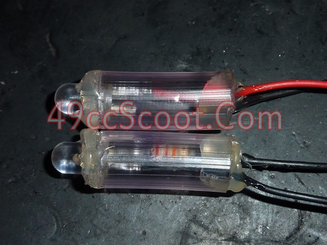 Homemade lamp post. 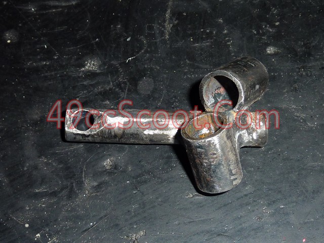 I think when I use it it's called a hot mess, not hot glue. 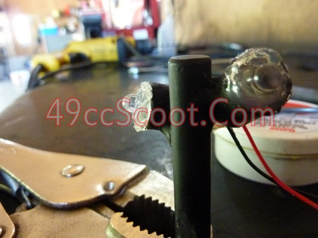 Now I just gotta wait about 7 hours till it's dark and I can see if it works. I was sticking a screwdriver through the "spotlight holders" to see where the screwdriver hit the face of the gauge and then tack welding. lol Would be smarter to do it at night, but I'm not that bright. 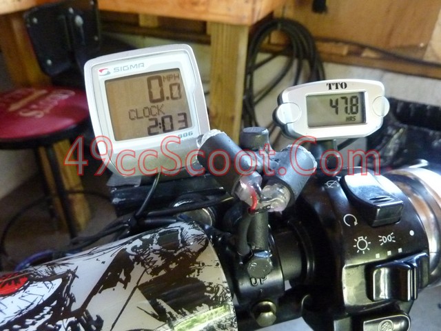 |
|
|
|
Post by 90GTVert on Jun 17, 2011 20:16:30 GMT -5
Spotlighting FTW! ;D The speedo is a little too close, but the bracket for it is cracked anyway so I'll make another at some point. I can still read it anyway. 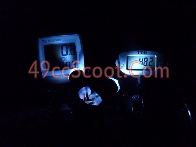 |
|
|
|
Post by 90GTVert on Dec 19, 2014 21:35:36 GMT -5
I tackled a little project tonight that I've had in mind for a while now- a light for my TTO CHT gauge! 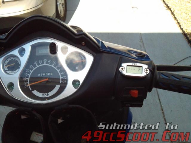 With the recent time change I've been doing more night driving and I've noticed it's really hard to tune and keep an eye on the CHT gauge in the dark since it has no backlight. Time to fix that! I built this little guy here. The blue part is the end of an ink pen with a single led from an old set of christmas lights. 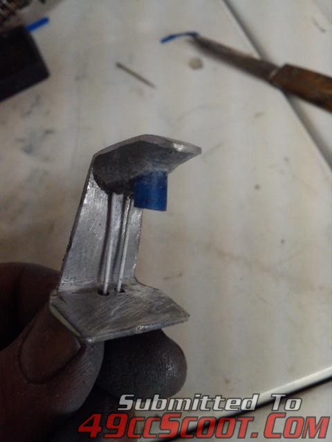 I found ground and 12v+ from the dash that comes on with the key and added this resistor to the + side of the led to keep it from simply popping when the key is switched on. 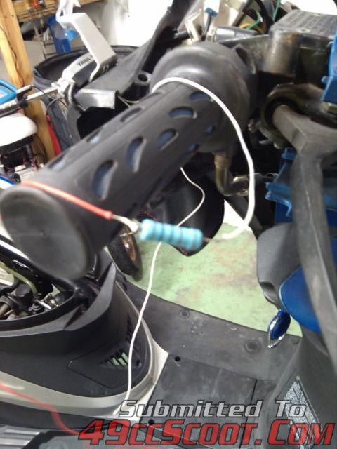 I'm pretty happy with how it turned out! It also doubles as a "dummy light" to remind me to switch the key off... 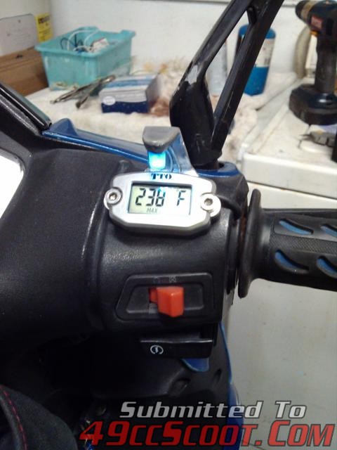 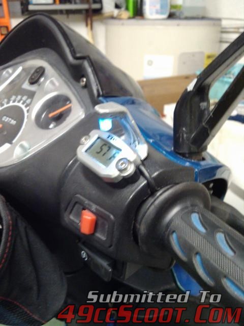 It looks pretty sweet in the dark and I can read the CHT perfectly now! 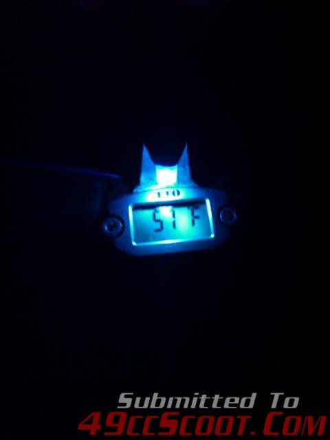 I finally found the other resistors that are the same as the one I used for the single led. (Bulb was from a set of led Christmas lights). 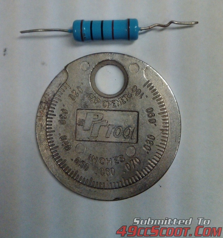 It's really hard to tell the difference between red and brown even when looking at it under a light, but this is a 5 band: brown, black, black, brown, (empty), brown. So that equals 1,001 Ohms with a tolerance of +/- 1%. The tolerance isn't too important as in this case it only equals a (possible) difference of 10 Ohms. The bulb was an led from a set of Christmas lights! Resistor goes on + side of led. (+ is the smaller of the tabs? filaments?- metal thingy's when looking inside the bulb)  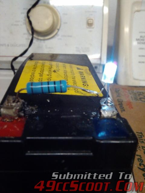 Deciphering resistor Values: www.freetronics.com.au/pages/resistors#.VJTgYf8AAB |
|
|
|
Post by ryan_ott on Dec 5, 2015 19:30:58 GMT -5
|
|