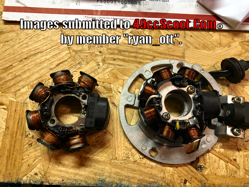
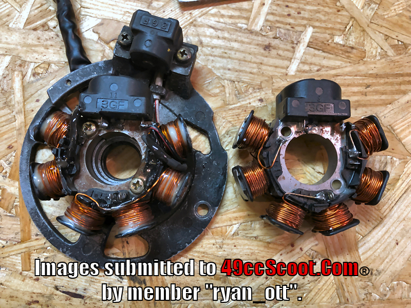
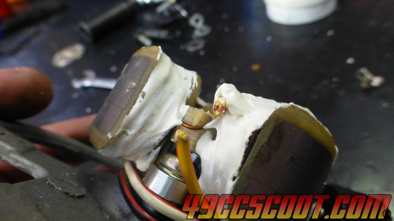
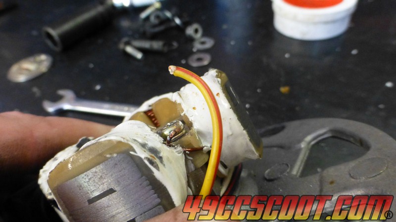
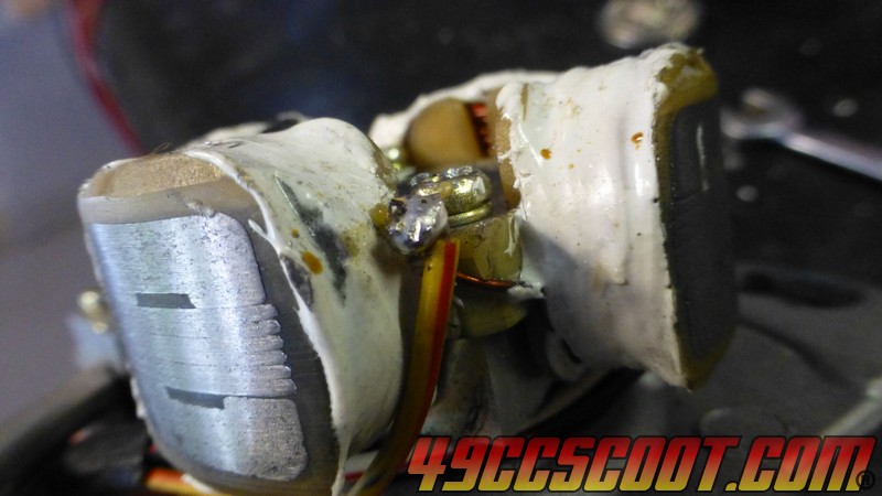
Since Ryan was kind enough to share the above post, I thought I should add info from my own posts that have been in T2's build thread for 7 months that I've never put in the Tech Library.
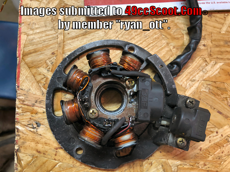
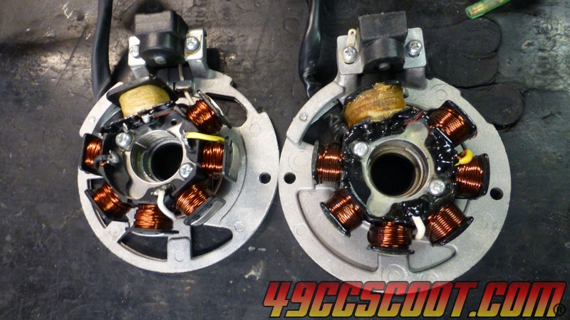
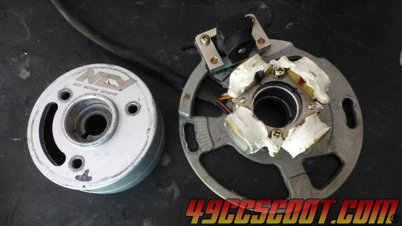
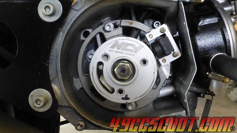
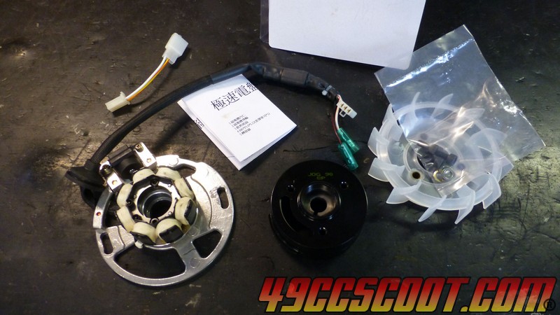
My first attempt at floating the ground on a stator was with a HOCA (same as some NCY) racing stator with a small flywheel for the Minarelli/clone 2Ts. It uses 7 small windings for charging/lighting, but some older models had only 3. They have reduced output compared to stock, with the advantage of a quick responding engine from the reduced flywheel mass. I thought that perhaps floating the ground and using a full wave rectifier would make it better for street use.
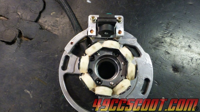
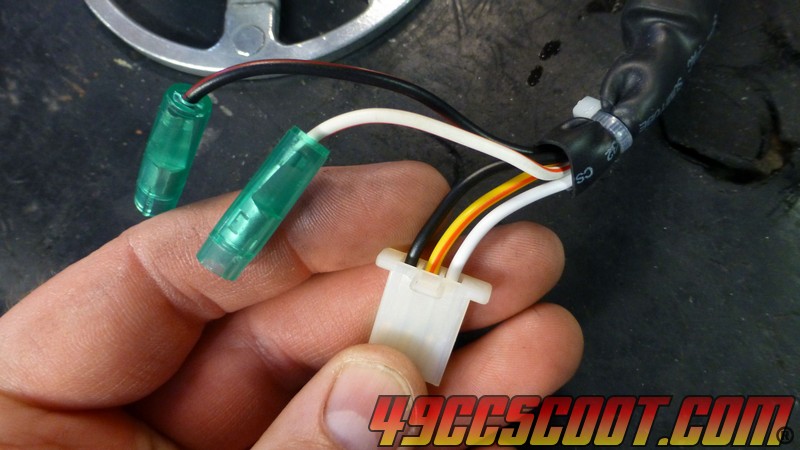
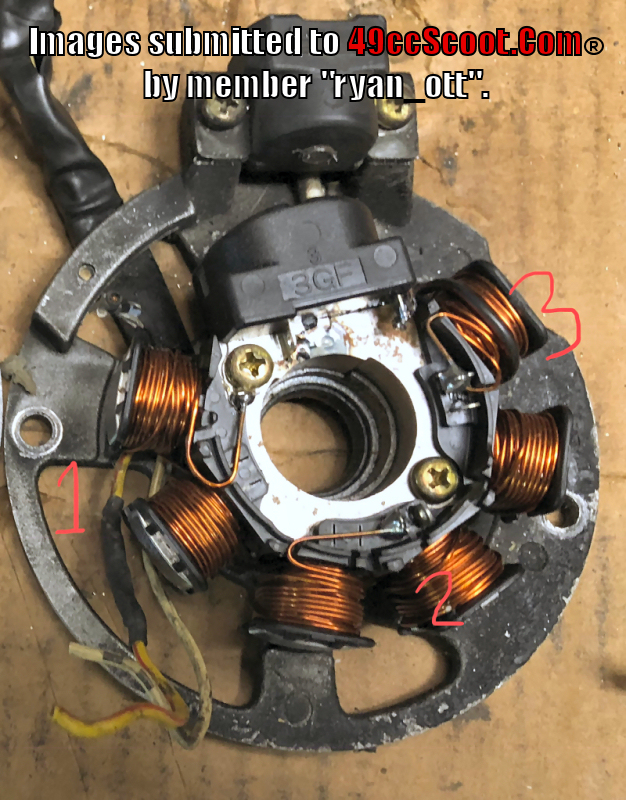
Here's a diagram of where wires are going that I made after my first look at it.
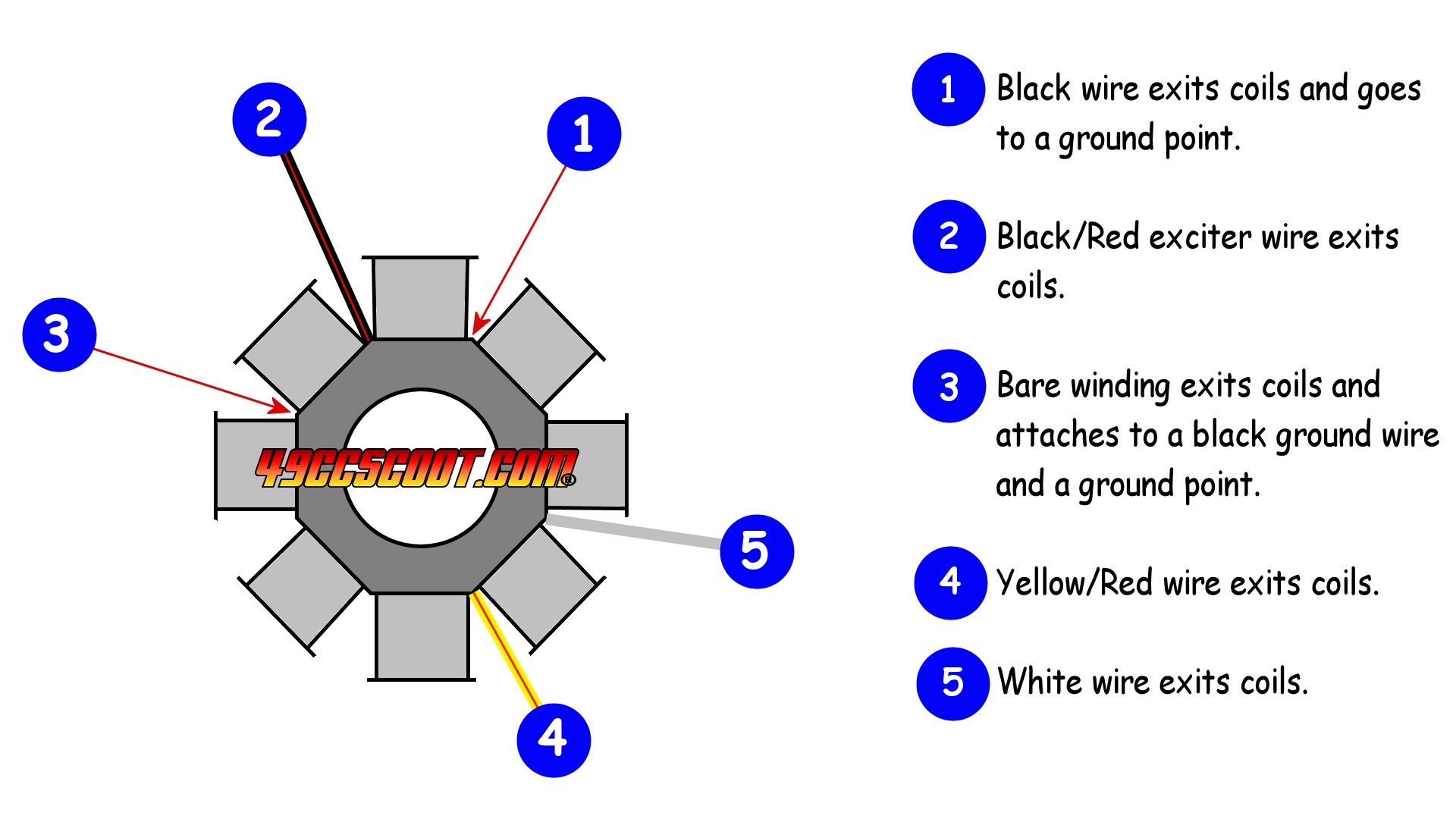
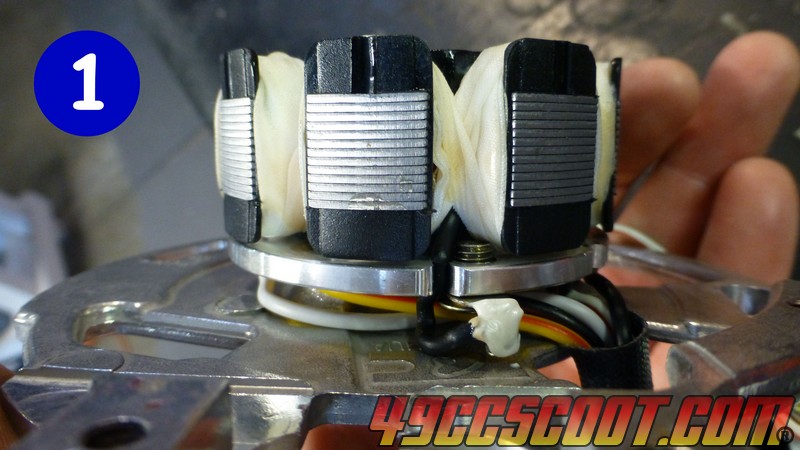
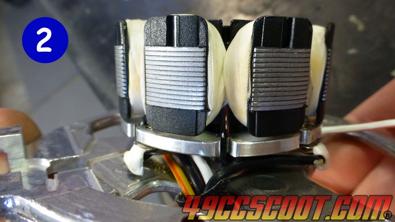
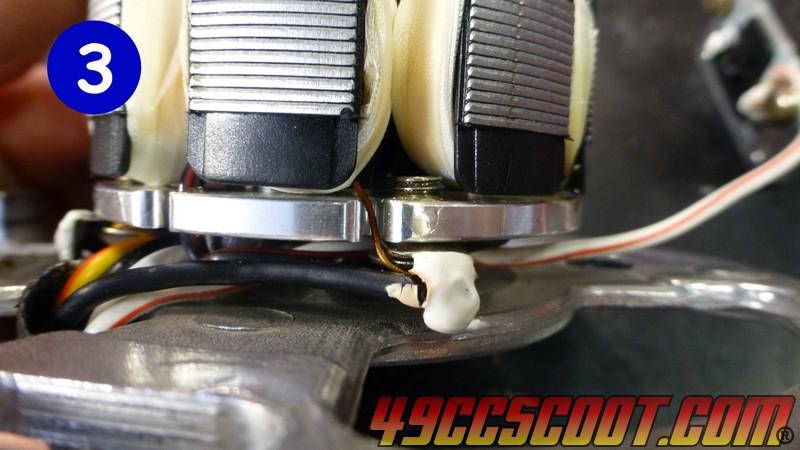
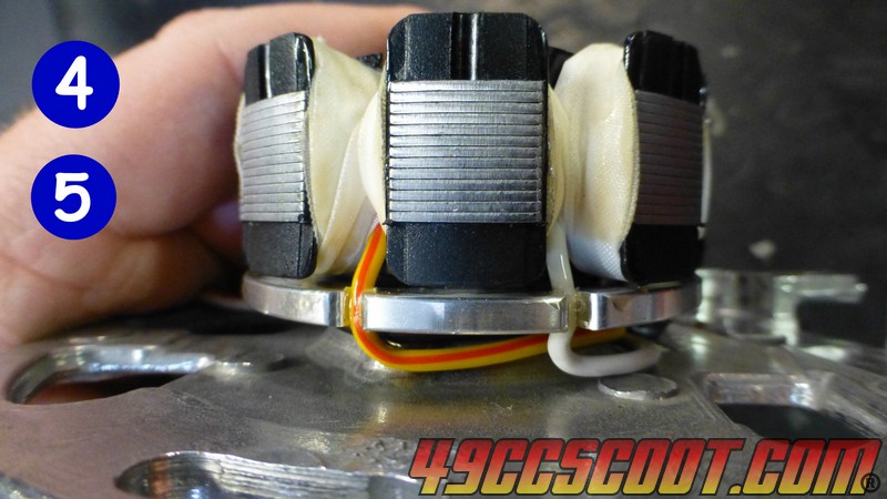
This is what I wanted to achieve to float the ground and ready the stator for use with a full wave rectifier.
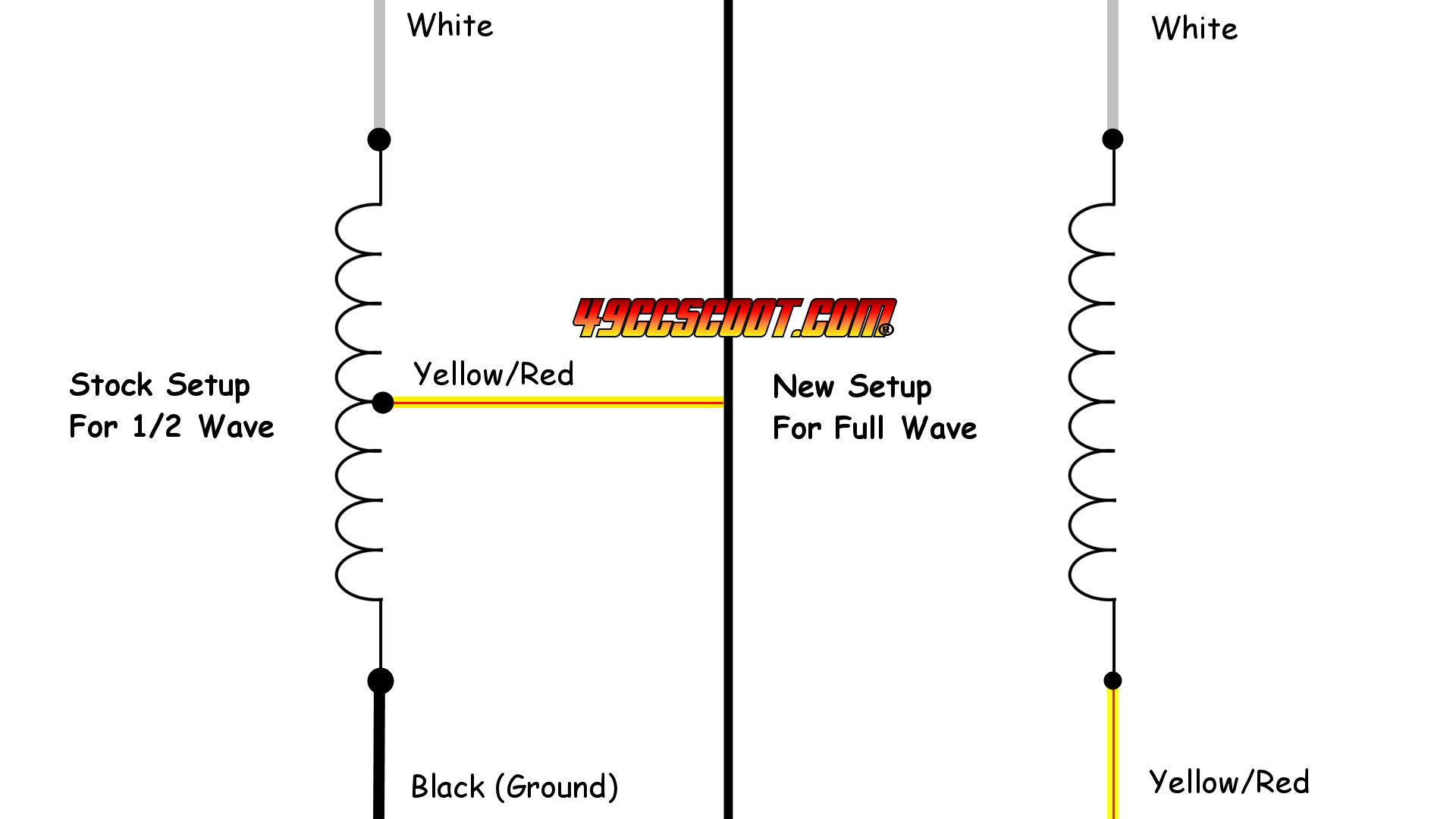
I checked and got 0.7Ω from yellow/red to ground and 1.7Ω from white to ground, so white should be the farthest away.
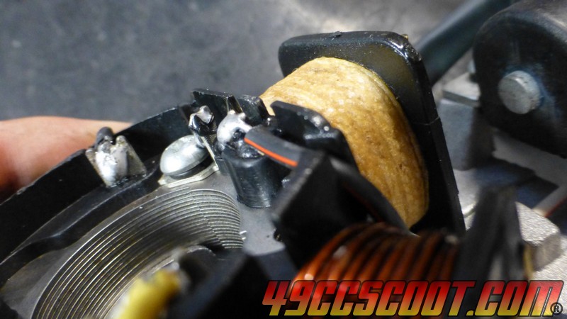
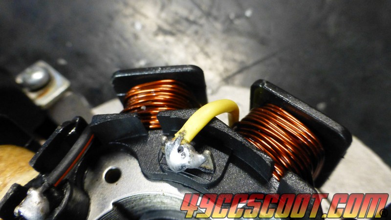
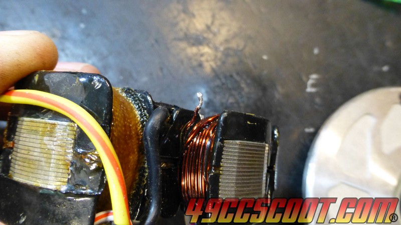
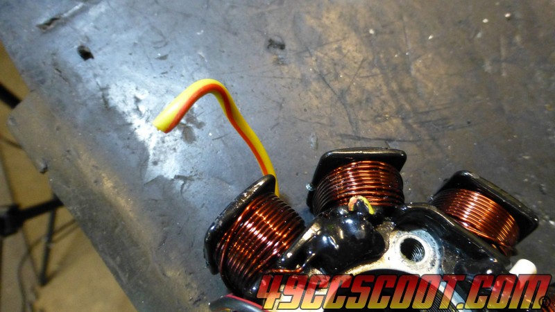
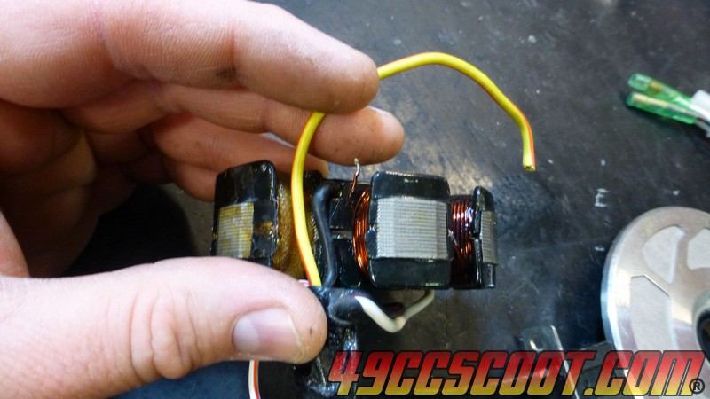
What I needed to do was to cut the bare winding before it reaches the ground wire (3). Then cut the yellow/red wire (4) off and run it over to attach to that bare winding (3).
Being my first time attempting this task, I wanted to explore a bit more to see if I was indeed correct on where everything went. This was not totally necessary, and I will show another conversion later without stripping the stator down so much.
I pried wires out of their little grooves and I could get the stator free a little, but it really didn't matter. Couldn't see anything for the wrap.
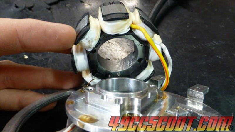
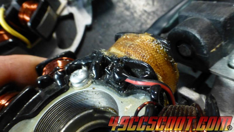
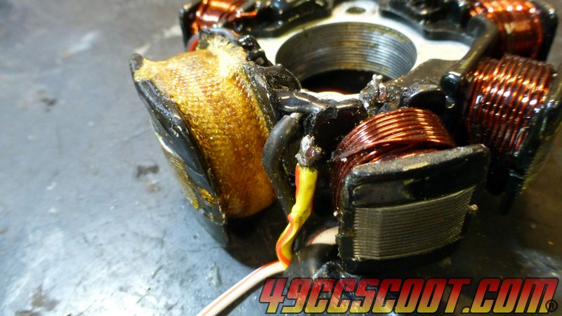
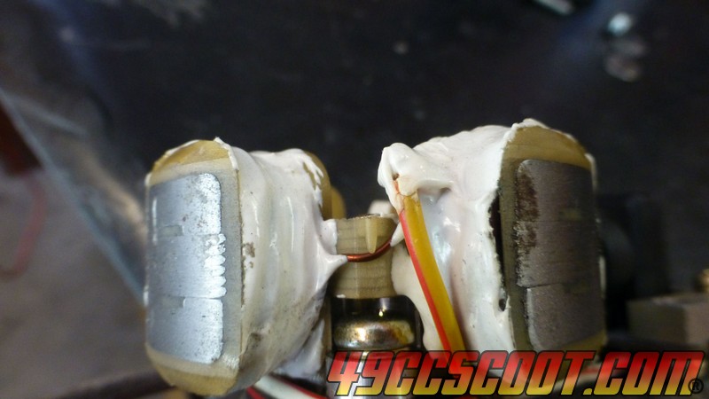
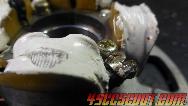
I stripped a bunch of fiberglass stuff off till I could see for sure what was up.
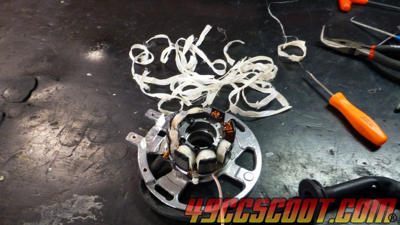
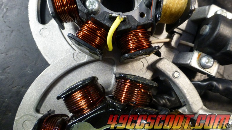
There are 2 exciter coils with fine wire windings.

The yellow/red wire is in the middle of the charging/lighting coils.
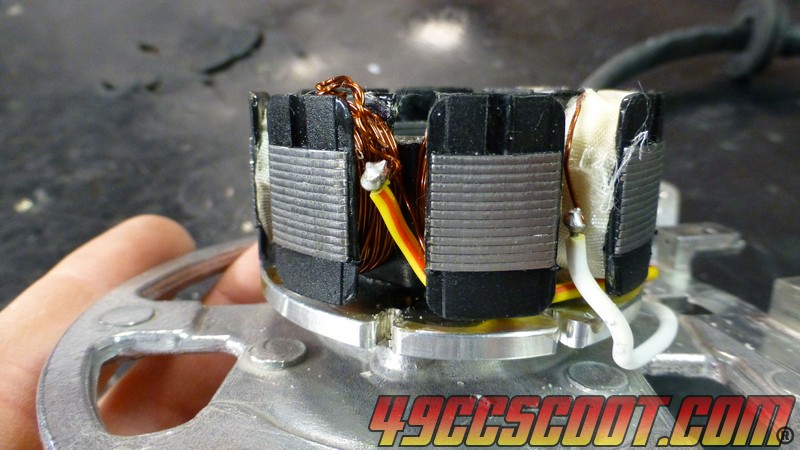
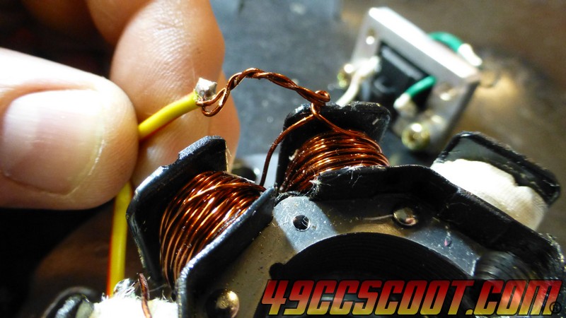
White ends one side and that bare to ground ends the other.
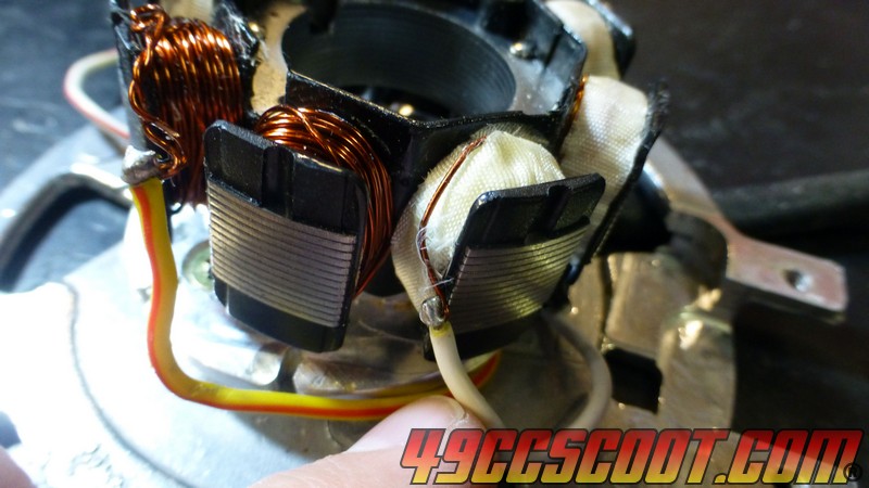
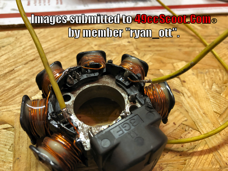
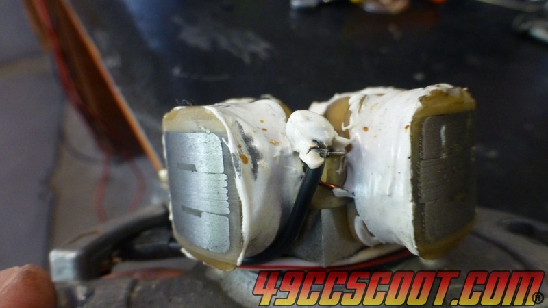
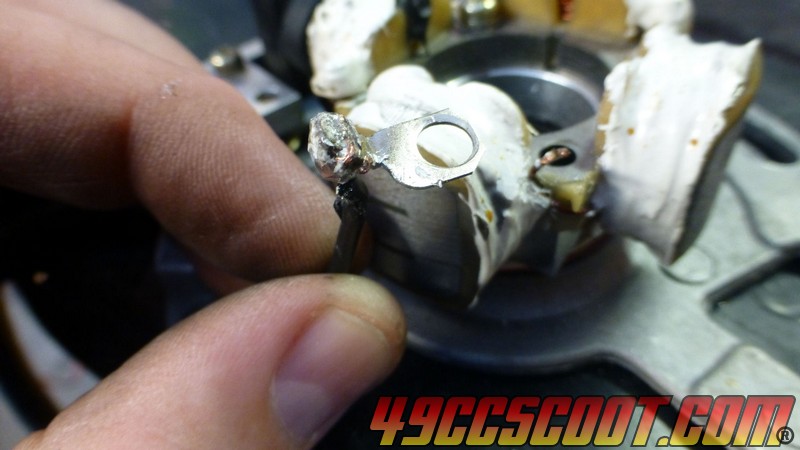
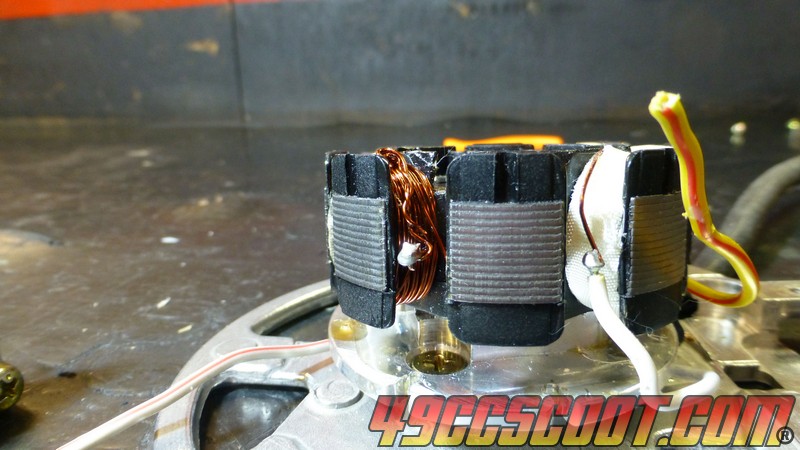
I cut the yellow/red wire off, leaving the ball of solder to be sure the 2 coils stayed joined.
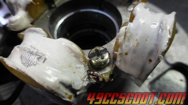
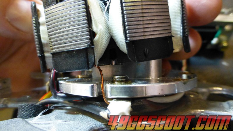
I cut the bare wire from the ground point.
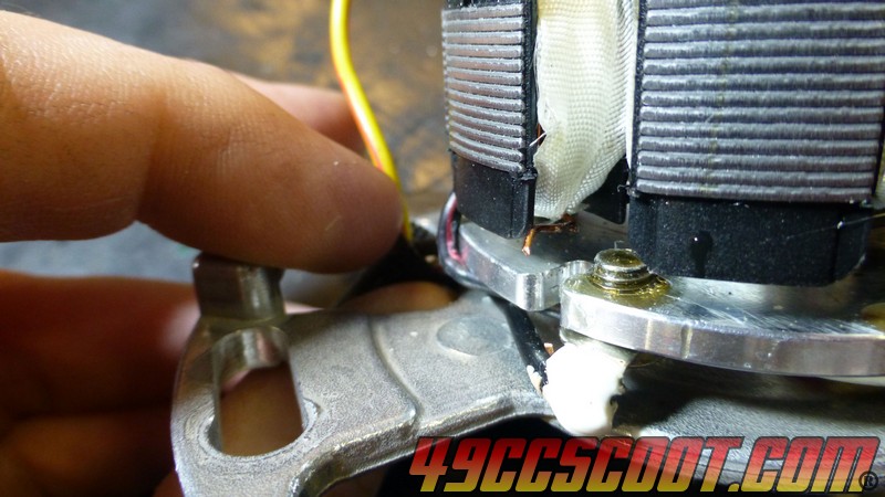
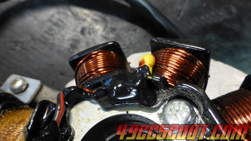
Soldered the yellow/red to the bare wire.
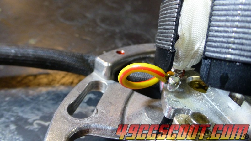
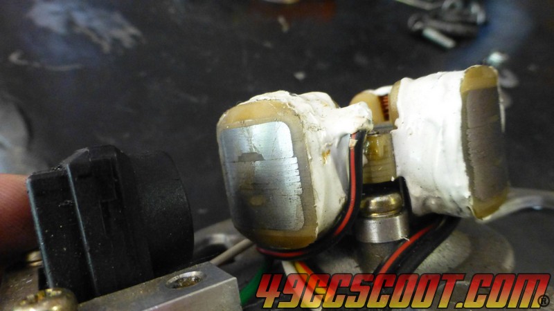
I wanted to seal the stator. The stock material appeared to be a really thin fiberglass cloth wrap with a little resin added in spots, so fiberglass should be one option for sealing. New connections needed to be covered with something as well, especially with one being near the chassis which would be a ground.
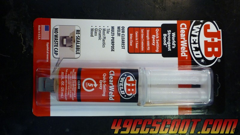
I went to Wal-Mart and picked up 2 JB Clear Weld for under $10. Turns out, if you use even 1 of these on the stator, you're gonna have a mess. At least on this little stator. All said and done I don't think I used 1/2 of 1 of these packs.
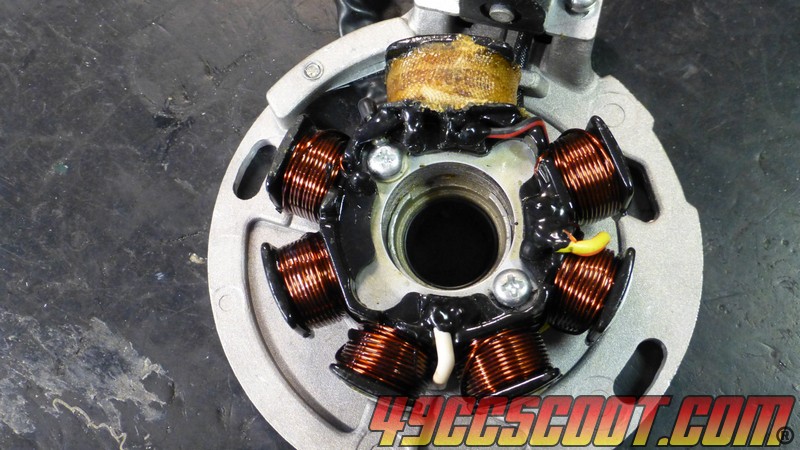
I started putting epoxy on the outward facing side of the stator. The extensions are there to hold a wire where it needed to be, because wires must be kept away from the rotating flywheel that will be installed over it on the engine.
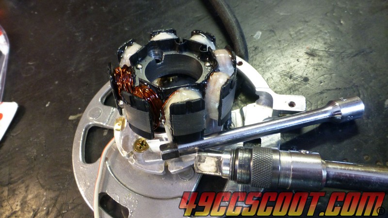
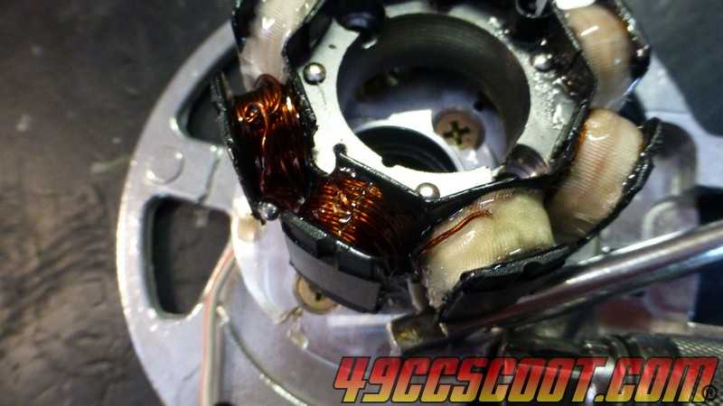
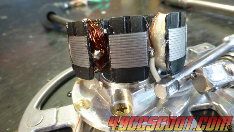
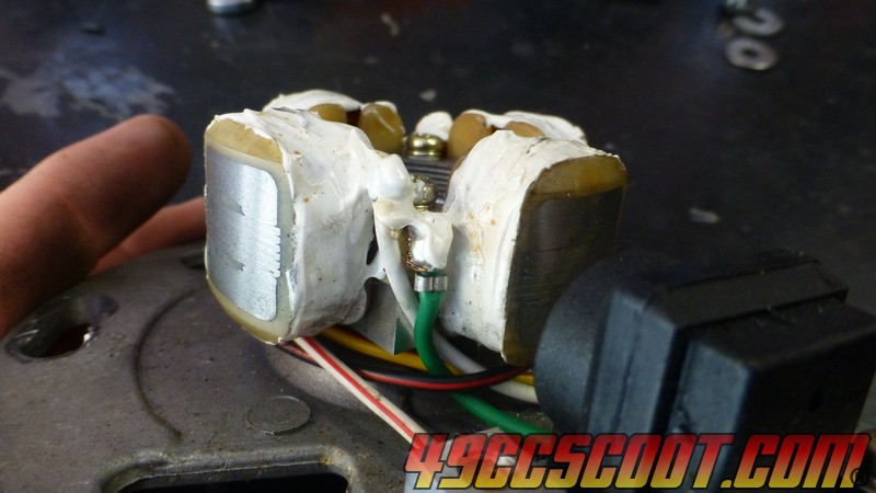
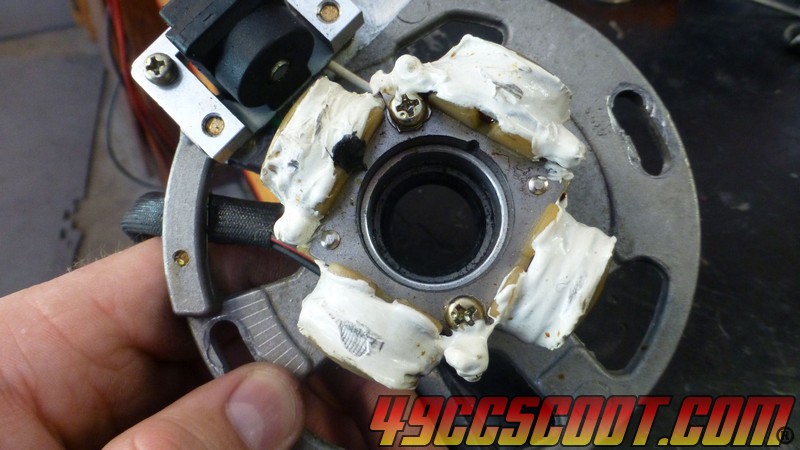
Later, I checked out the epoxy that was applied. I went a bit wild I suppose, because it puddled and formed globs in spots from running. Nothing that caused a problem though.
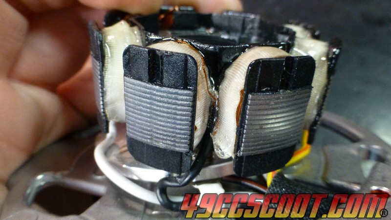
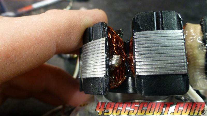
I flipped the stator over and propped the plate up and applied epoxy to most of the other side.
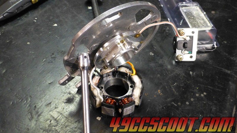
Off and on for 2 days, I finished up coating the stator and got it back together. It doesn't take long each application, just had to wait between them so I didn't flip it over or re-position it and epoxy the stator to the workbench or something. Would be easier if the whole stator was off of the plate, but not a big deal and not worth the risk of stripping off really tight cheap screws to me.
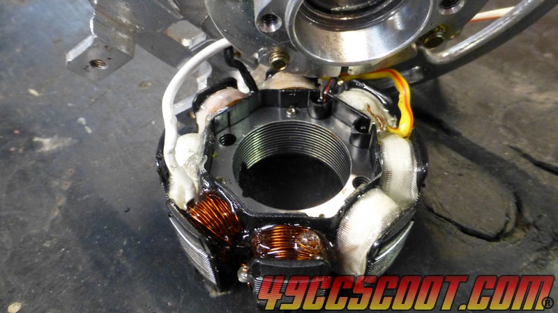
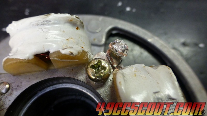
I put a few layers over this area for extra insulation, being paranoid about it being near the plate which would be a ground.
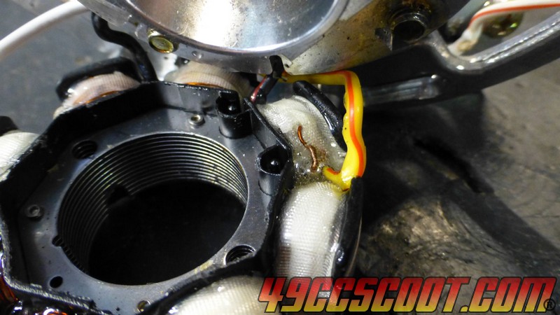
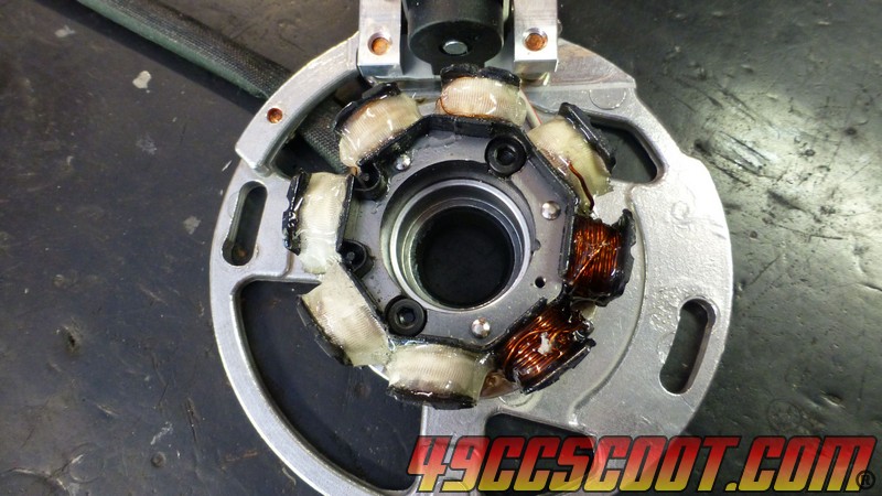
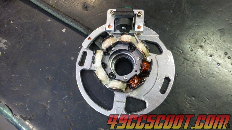
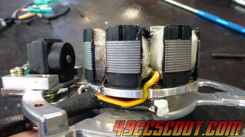
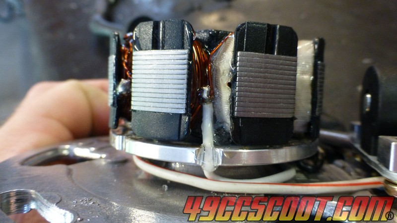
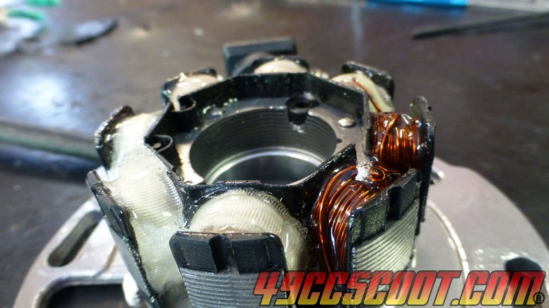
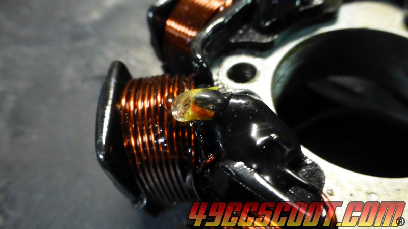
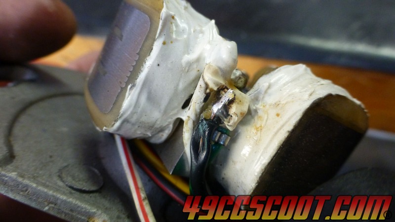
Once it was back together, I was curious about the lump in the stator wiring. I thought perhaps it was a connector that I could get rid of. After stabbing myself in the tip of the thumb with a utility knife, I removed the heat shrink and this is what I found. I couldn't tell you what it does with any certainty, but it's on the exciter coil wire and attaches to the ground going to those coils as well. Nothing of concern for the process of floating the ground.
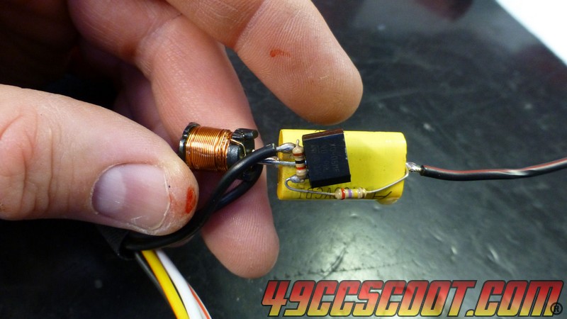
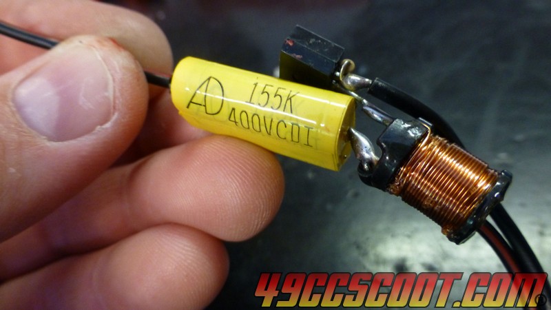
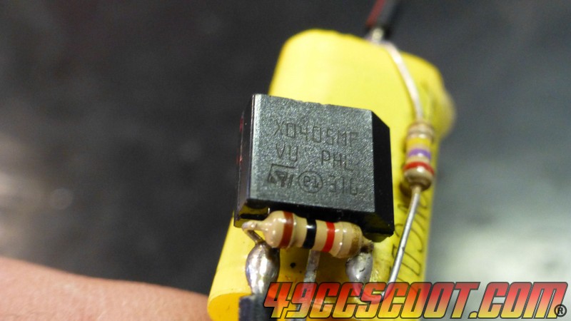
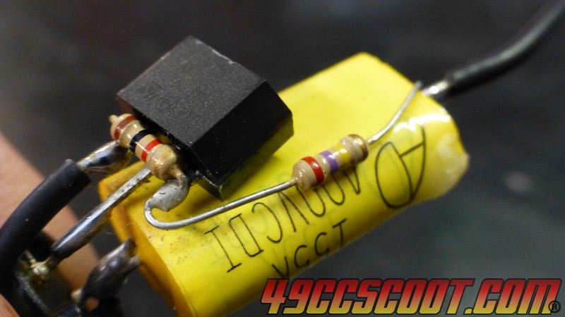
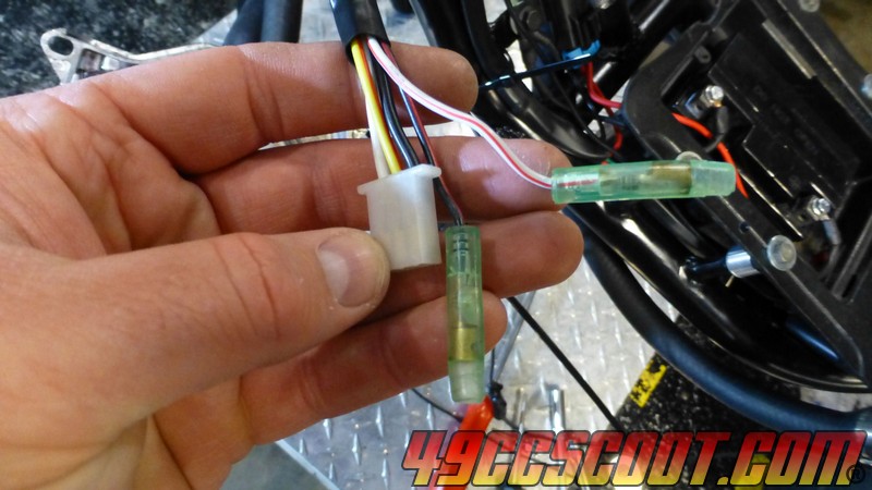
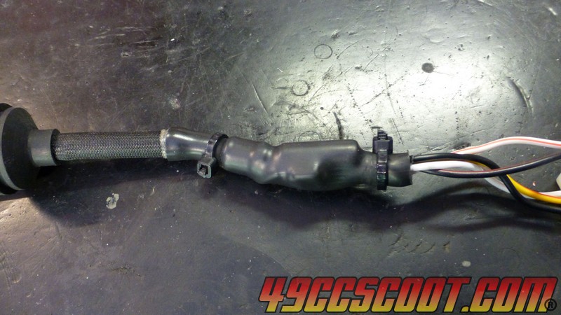
Luckily I ordered some big heat shrink when I bought wiring supplies some time ago, so I recovered it.
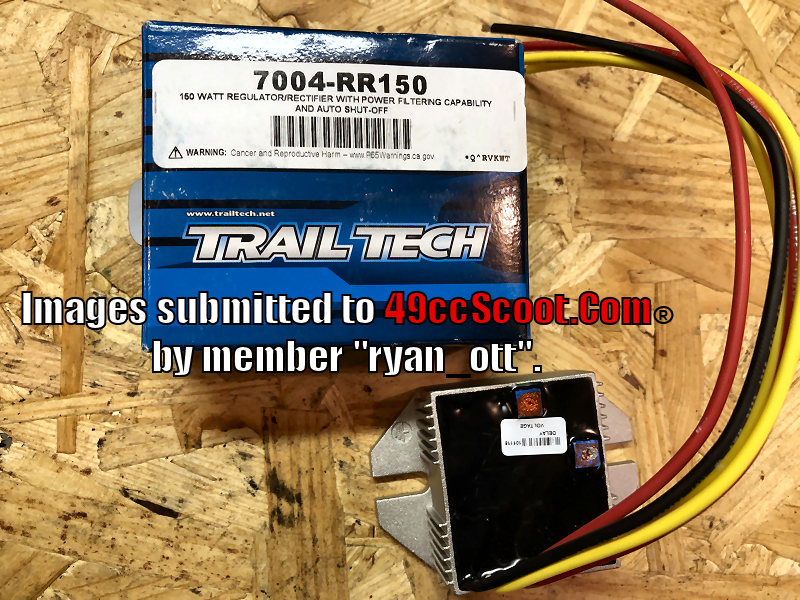
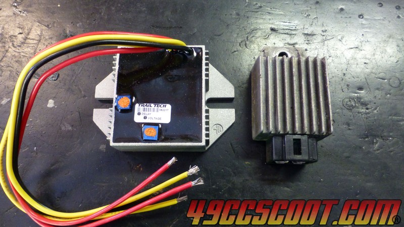
I used a Trail Tech 7004-RR15 full wave regulator/rectifier for my conversion. The Trail Tech rect/reg is larger than the stock unit and the wires stick out in a different way, so it wouldn't just fit where I had the stock one and had to be mounted in a different area. This was of little concern to me, because I built an entire wiring harness for the scooter from scratch as part of a larger project and to accommodate the changes needed for the new regulator and making my headlights work on DC battery power instead of AC from the stator as it used to be.
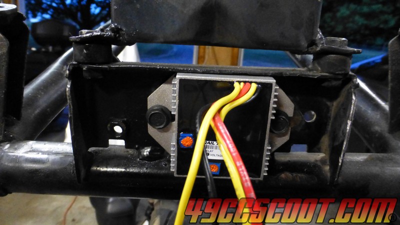
Since I've mentioned wiring changes, let me give you a little more info on that. Generally, one of the major selling points of a full wave conversion on small scooters is the ability to switch the headlight(s) over to DC battery power. The majority of small scooters use AC power direct from the stator to power the headlight(s). It is regulated to keep voltage at a safe level to prevent blowing bulbs, but otherwise goes straight to the headlight circuit. This usually means the headlight gets very dim at idle. As long as the headlight doesn't demand too much power, it will get to full intensity once the engine revs enough for AC output to increase. I've used around 100 watts of headlights on the stock AC system before without any complaints at cruise RPM with a stock stator. Smaller stators, like the one that I am modifying here, may struggle to illuminate much more than 50W to full brightness from past experience. Swapping to DC from the battery for headlight power allows the headlight(s) to be at full brightness all of the time. I can't say that it ever really bothered me for my incandescent lights to dim at idle, but LED lights will usually flicker at idle or low RPM. The only possible perk of this is being noticed, because it did seem to draw the attention and stares of others at times. They continue to flicker at even high RPM, but it is generally at a frequency too high for the human eye to even notice it. Constant DC power from the battery keeps LED lights steady and bright at idle.
For this reason, power to the headlight needs to be switched over to battery power, preferably fused and switched for circuit protection and to eliminate the possibility of leaving the lights on and draining the battery. You can just run a wire with a fuse from the battery to the headlight switch in most cases for the simplest form of a conversion, or use an ignition switched battery power source or use a relay to trigger battery power to the headlight circuit when the key is turned on.
The Trail Tech 7004-RR150 regulator/rectifier makes headlight circuit power very simple. It includes an output for lighting that only switches on when it senses that the engine is running. Just connect that wire to the headlight switch's positive power input, with a fuse inline to protect the circuit. Make sure the fuse is large enough to support the lighting that it needs to, but small enough to fail before your wiring does. I tend to use wires rated for much more current than any accessory needs, and then use a fuse just above what the accessory needs so the fuse would fail way before the wiring was in any danger ideally. It only takes a few minutes to add an inline fuse, so don't lose your entire scoot to a fire if something bad happens because you didn't feel like adding a fuse holder and fuse.
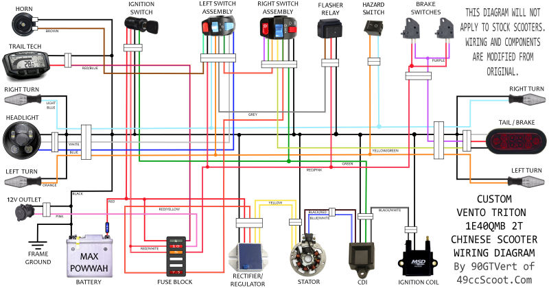
Changing wiring to the regulator from the stator is usually quite simple and will vary from scoot to scoot. Here's a wiring diagram that I drew up to give me something to build from when I did my project.
Click for full size.
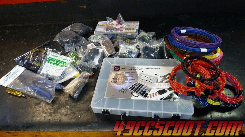
Building a whole new harness is way overkill and a lot of effort, as well as potentially a considerable amount of money. I spent over $200 building a harness because I wanted to use quality wiring and sealed connectors everywhere. At very least, use good quality wire (even if just for a simple move). If you decide to go big like me, here's the source I used for GXL wiring in various colors and for wires with stripes to allow color coding more circuits than solid colors only would allow :
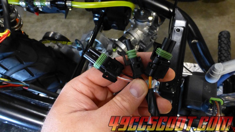
LINK. I used weather pack connectors on most of my connections. They're very high quality and support a large range of wire sizes, but they are very large and harder to hide. If I did it all over again, I would consider metri-pack connection that are smaller in size and capable of supporting most connections for the scooter.
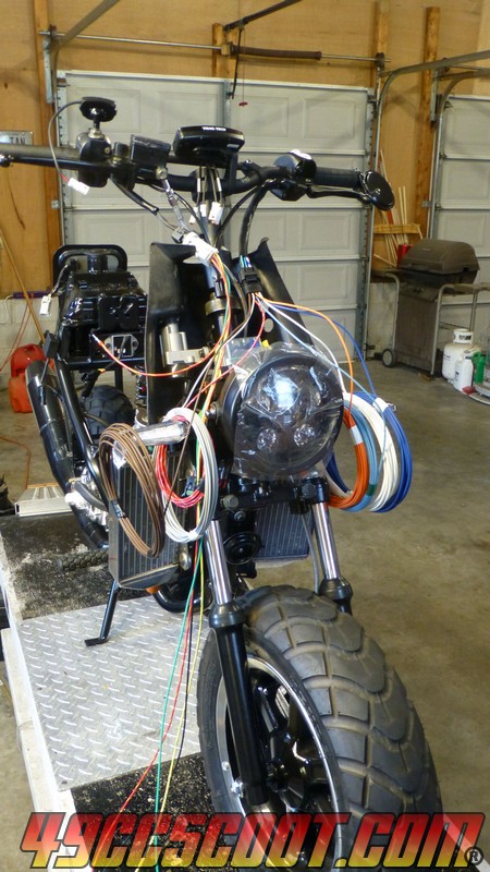
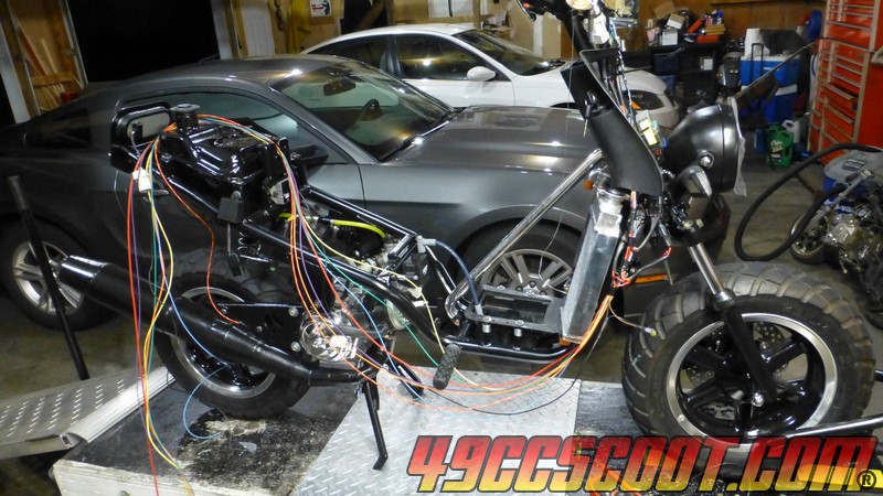
Here are my regulator and stator with weather pack connectors added.
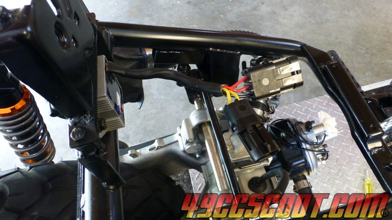
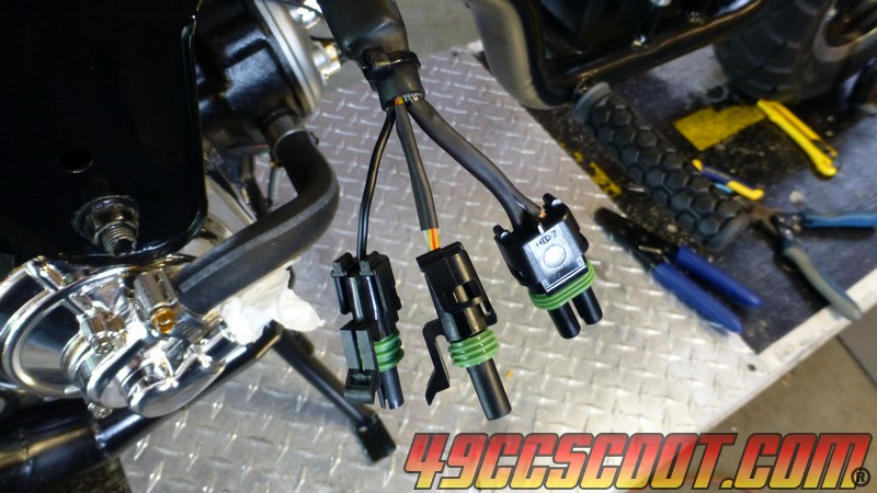
Once my harness was complete, I tried to fire up the scooter. My headlight circuit activated, so there was charging power. That's the good news. The bad news is that I had no spark. I tested and swapped and the end conclusion was that there was an issue with the stator. This was a brand new stator, never used before. I didn't mess with the exciter or pickup, the circuit related to creating and triggering spark. In the end the conclusion was that the stator probably never worked from the start. This leads us to an important lesson. Always try the stator that you're going to use before you do a conversion. Make sure it creates a spark and allows the engine to run (preferably tested under load aka real world or a dyno) and that it produces charging power. Otherwise, you may go through the effort of floating the ground for nothing and no one is going to take your stator back for a return/exchange after it has been modified.


