|
|
Post by frost1003 on Oct 28, 2020 22:07:55 GMT -5
Hi,
I bought a Tomberlin 150cc gy6 scooter recently with a no spark issue. I installed a new stator. I've had to change wires to get the original connector to work. There are 3 white wires coming from the wiring harness. And there are 3 different color wires coming from the stator. There's a connector for these 3 wires.
Is there any specific pattern for the 3 white wires coming from the wiring harness and the 3 colored wires coming from the stator to be connected?
I'll see if I can add a picture?
Unfortunately the person who owned the scooter before me started cutting and pulling wires to try get the no spark issue fixed.
But they didn't find the actual issue. So I'm having to fix their wire hacks and trouble shoot the original issue. Thanks for any ideas or videos to point me in a good direction.
|
|
|
|
Post by frost1003 on Oct 30, 2020 22:12:59 GMT -5
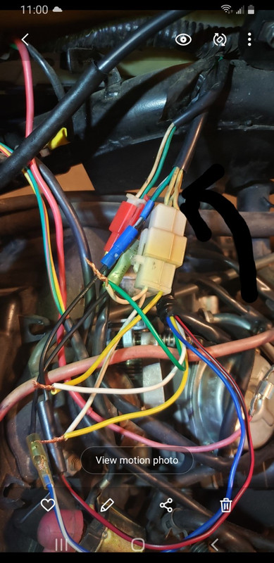 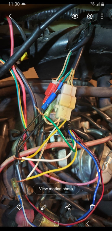 So the arrow points to the connector with the 3 white wires coming from the wiring harness. I took the other half of the connector from the original stator so I can easily connect the new stator wires. |
|
|
|
Post by snaker on Oct 31, 2020 10:52:03 GMT -5
Ya got quite a mess goin on there.
The wires at the arrow, that's the chassis side? Aren't they yellow?
Looking at a picture is mostly guessing.
That chassis harness? seems to be a 3 phase setup?
That stator side? grn, wht, yel seems to be a setup for a single phase, half wave (double guess)
These magneto systems require a matched set of stator and RR (regulator/rectifier)
Guessing on what you actually have, I would guess that you trying to match a single phase, maybe half-wave stator to a 3 phase RR. You can't
I wouldn't fire it up with the grn wire connected to the wht?.
Best to put a multi meter on it.
|
|
|
|
Post by snaker on Oct 31, 2020 10:58:52 GMT -5
Trying to see what's what in the picture.
That grn in the chassis harness?, does that splice to a blk, then to the red/blk from the stator? If so, that just don't seem right.
Grn is usually chassis ground and the red/blk is usually the AC CDI power wire off the stator. Again just guessing.
|
|
|
|
Post by frost1003 on Oct 31, 2020 23:24:27 GMT -5
Thanks for the feedback. I actually made progress. There's a youtube video I watched on testing a stator with a multimeter.
He identifies all 5 wires from the stator and I got it figured out. I got it to spark today. I didn't crank it up because there's some carb issues. The old owner cut the wires trying to bypass the CDI box.
What I believe happened is the oil drain plug had a crack in the metal. The oil leaked and got slung up on the motor. Some oil got in the stator and messed it up from what I could tell.
I put in an identical 8 pole stator and got all the wires connected properly. The pickup was too far away from the fly wheel. Loosening the bolts to reposition the pickup didn't work. I had to prey it down to get to approx .010 of an inch. That seems to have worked for fixing the wiring issue. Thanks.
|
|
|
|
Post by snaker on Nov 1, 2020 11:02:49 GMT -5
Good job.
|
|
|
|
Post by frost1003 on Nov 7, 2020 12:10:34 GMT -5
Well, I had spark and than it quit. I have tested many parts and checked the wiring harness and ground points.
I'm stumped because I've tested with a multimeter the following parts and they're working:
Brake level switches, ignition switch, kill switch, starter solenoid, and stator power output is good.
I've replaced the spark plug coil and CDI. The battery is fully charged when testing these things.
The starter turns the motor over and I get a good reading from the stator. The blue/white pickup wires is 0.5 VAC, and the red/black exciter wire puts out 51 VAC.
Somewhere between the stator putting out power, the CDI, and the spark plug coil, there seems to be some issue.
When I put my multimeter ground lead on the negative terminal of the battery, and put the positive lead on the hot wire of the spark plug coil and turn the engine over, I don't get a reading on the multimeter. I don't think there's power getting sent to the spark plug coil.
I've gone through the No Start Tutorial on here and checked a few other resources.
I dug into the wiring harness and checked for bad wires all along it. I taped up a few spots to be sure they're good.
Thanks for the help!
|
|
|
|
Post by frost1003 on Nov 8, 2020 1:02:06 GMT -5
I've spent some time working on identifying the no spark issue. I discovered there seems to be an issue with the kill switch after all. It got where it won't turn off the dash or head light in the off position. I'm going to replace it.
|
|
|
|
Post by frost1003 on Nov 10, 2020 22:55:57 GMT -5
I've also purchased a whole wiring harness on Ebay for $40. There's still an issue and I hope rewiring the scooter and replacing the main electrical components will fix it. To me $40 isn't that expensive for every thing.
|
|
|
|
Post by frost1003 on Nov 21, 2020 11:39:06 GMT -5
Well I have discovered a few bad wires in the original wiring harness. There were 3-4 spots where the green wire had the rubber split. It seems to have been enough of a grounding issue to create a no spark condition. I've taped up bad spots and got it running. I cut open about 2.5 feet of wiring harness to check the wires.
|
|
|
|
Post by jloi on Nov 21, 2020 11:49:32 GMT -5
I too bought a whole harness - just so I could cut it open to see it . but since I'm electrically challenged and I'm trying to go naked and bought new handlebar switches and did away with the whole cluster it's slooooowww going for me trying to figure out the switch wiring and the motorcycle headlight I bought just complicates things even further. looks like you're doing good .
|
|
|
|
Post by frost1003 on Dec 3, 2020 22:38:38 GMT -5
The YouTube videos that isolate a part and show its wired/works are helpful. A wire striping tool and a roll of heat shrink are very useful. The wire colors sometimes match, but a new wiring harness may have different connectors or corols for the same wires. Can be a pain.
|
|


