|
|
Post by fuzzybabybunny on Mar 6, 2021 1:11:15 GMT -5
Has anyone used one of these 5-wire full wave regulator rectifiers before? I was told to use this for my 110cc Honda Wave full wave conversion.  I understand all the wires except for the black one. What's the point of having the black wire connected to the ignition switch circuit? The ignition switch circuit shuts off the CDI which shuts off the bike. Why would you need the regulator-rectifier to *also* be on the same circuit? 😕 |
|
|
|
Post by FrankenMech on Mar 6, 2021 6:27:16 GMT -5
That one would not work for your conversion. I told you that you would need matching parts. You will have to do the research. You need a regulator with three AC inputs. Some regulators have more than 5 wires, some with 6 or even 7. In this 5 wire regulator the keyswitch input probably powers the regulator circuits to keep it from draining the battery like the 4 wire shunt regulators do. Keep looking. That regulator was just the first one I found that had more than 4 wires, it is for a gy6 application not your honda. Again, keep looking and maybe look on parts vendors sites.
|
|
|
|
Post by snaker on Mar 6, 2021 18:17:18 GMT -5
Has anyone used one of these 5-wire full wave regulator rectifiers before? I was told to use this for my 110cc Honda Wave full wave conversion. I understand all the wires except for the black one. What's the point of having the black wire connected to the ignition switch circuit? The ignition switch circuit shuts off the CDI which shuts off the bike. Why would you need the regulator-rectifier to *also* be on the same circuit? 😕 The magic black is a battery sensing wire, installed after the switch for switched voltage sensing. If you have converted to full wave (assuming this goes along with your post of doing just that), and this is a full wave RR, then yes, it should do. I have the identical looking one with the pink wire, no worries there, pink is the same as white. |
|
|
|
Post by fuzzybabybunny on Mar 10, 2021 13:04:45 GMT -5
Has anyone used one of these 5-wire full wave regulator rectifiers before? I was told to use this for my 110cc Honda Wave full wave conversion. I understand all the wires except for the black one. What's the point of having the black wire connected to the ignition switch circuit? The ignition switch circuit shuts off the CDI which shuts off the bike. Why would you need the regulator-rectifier to *also* be on the same circuit? 😕 The magic black is a battery sensing wire, installed after the switch for switched voltage sensing. If you have converted to full wave (assuming this goes along with your post of doing just that), and this is a full wave RR, then yes, it should do. I have the identical looking one with the pink wire, no worries there, pink is the same as white. Hmmm... I'm confused.
I bought two regulators:
- five wires, red, green, white and pink for VAC, and black
- four wires, red green, white and pink for VAC
So which one should I be using? I've already installed the five wire one and it works fine, but why wouldn't the four wire one work as well? Both are for single phase full wave, which is what I converted my stator to outputting. |
|
|
|
Post by snaker on Mar 10, 2021 14:37:11 GMT -5
Thats when you have to know what your buying, from a vendor that is helpful.
4 wire RR's come in fullwave and in also setups for the dual circuits.
Find out what you got.
|
|
|
|
Post by FrankenMech on Mar 10, 2021 19:52:11 GMT -5
Just because the Chinglish ad copy says 'rectifier' does not make it true.
|
|
|
|
Post by fuzzybabybunny on Mar 11, 2021 4:29:20 GMT -5
Thats when you have to know what your buying, from a vendor that is helpful. 4 wire RR's come in fullwave and in also setups for the dual circuits. Find out what you got. In my part of the world no one knows anything about these regulator rectifiera and the boxes they come in are blank. I asked one of the Filipino YouTubers who made a full wave conversion video and he said any four wire reg-rec will do, provided it's not one of those with only the four metal contacts and not actual wires. I've tried both the four wire and the five wire now and measured the current going to and from the battery for each and the associated voltages. There was no appreciable difference between the four wire and the five wire. The current varied a bit more with the 4 wire. When the bike is off, the four wire also wasn't draining the battery. The multimeter sometimes read -0.1 mA, but it reads that with the probes disconnected from anything as well. The five wire regulator had the same readings. |
|
|
|
Post by snaker on Mar 11, 2021 13:29:35 GMT -5
Well, that's pretty much what you have to do.
You already ran it and nothing burned up, so far so good.
Put a voltmeter on the battery + connection.
With a healthy battery, you should see approx:
Key off: 12vdc something
Key on, start on: volts dip down towards 10's, the healthier the higher
Key on, engine running: should see a steady climb to 13-14.5vdc
Try to get some runs on it and monitor for excess heat.
Better yet get a small dc voltmeter and permanently install where you can monitor it on the fly.
|
|
|
|
Post by fuzzybabybunny on Mar 11, 2021 21:31:49 GMT -5
Well, that's pretty much what you have to do. You already ran it and nothing burned up, so far so good. Put a voltmeter on the battery + connection. With a healthy battery, you should see approx: Key off: 12vdc something Key on, start on: volts dip down towards 10's, the healthier the higher Key on, engine running: should see a steady climb to 13-14.5vdc Try to get some runs on it and monitor for excess heat. Better yet get a small dc voltmeter and permanently install where you can monitor it on the fly. Right, I'm just not clear what difference that fifth black wire makes on the five wire regulator. I already figured that both styles of regulators would work since both are used in tutorial videos, but I can't see the difference between the two after measurement. The four wire isn't leaking current while the bike is off like other people claim it does, and both seem to charge and regulate voltage in the same way. |
|
|
|
Post by snaker on Mar 12, 2021 0:20:39 GMT -5
I dug up these during my searches 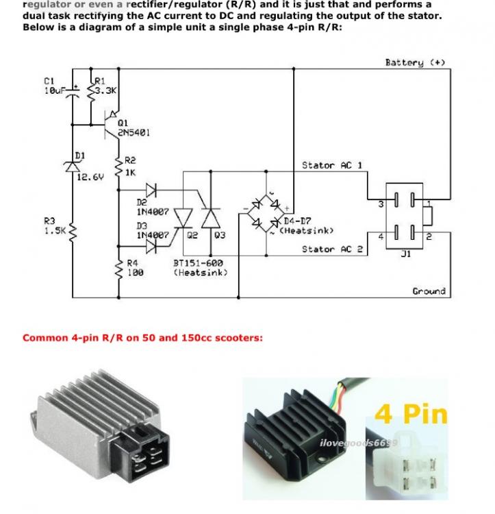 This one is a full wave 4 pin. Note the full wave bridge rectifier section 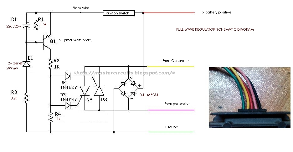 This is the 5 wire. A bit hard to follow. The external wires aren't straight on the right side. At the top the black 5th wire goes external and to the ignition switch on the switched side. Again the full wave rectifier is obvious On both of these the two AC wires coming from the stator are equal legs and the ground in lighting circuit is only introduced inside of the RR. |
|
|
|
Post by FrankenMech on Mar 12, 2021 5:49:56 GMT -5
The rectifier only feeds the battery and the regulation is done with the shunt regulator Q2, Q3. The black wire setup isolates the voltage divider network from the battery through the ignition switch. That isolation helps battery drain while the engine is off.
With a full wave rectifier system the AC (usually 3phase) is fed through a rectifier section first then through a regulator to the battery and system. The AC stator windings are not grounded.
|
|
|
|
Post by fuzzybabybunny on Mar 19, 2021 1:20:25 GMT -5
The rectifier only feeds the battery and the regulation is done with the shunt regulator Q2, Q3. The black wire setup isolates the voltage divider network from the battery through the ignition switch. That isolation helps battery drain while the engine is off.
With a full wave rectifier system the AC (usually 3phase) is fed through a rectifier section first then through a regulator to the battery and system. The AC stator windings are not grounded.
I checked the battery drain with the 4 wire and compared it to the 5 wire. There was no difference. Neither had any drain, which is why I'm confused. |
|
|
|
Post by FrankenMech on Mar 19, 2021 3:26:14 GMT -5
More sensitive instruments or methods are required. Look at the voltage divider network. There is a reason for the black wire. They did not put it there for fun.
|
|


