|
|
Post by ashtoncox on Jan 8, 2023 16:06:48 GMT -5
Hello everyone! Hope your year is going well!
I have been having issues with my 50cc for a few months now and still have not figured out the issue. The issue is that occasionally the bike hesitates and then eventually dies. If you then try to start it again it will only idle. But we found that this only happens when the battery is dead and it is not fuel or valve related because it only happens when the battery is low from using the headlights for too long and as soon as you switch the lights off the bike runs completely fine again.
So far I have changed:
Carburettor
Spark Plug
Regulator Rectifier
Stator
CDI
Battery
Also the battery slowly creeps up to 13.5 volts at idle and not instantly jumping up to 13.5 while idling like it should. This is because the voltage from the Regulator Rectifier is too low because it has a low input from the stator (6-9 volts when it should be 20-30 volts). The weird issue that I have is that when I check the stator voltage when it is unplugged, it produces 20-30 volts at idle but once it has been plugged in it only produces 7-9 volts. I also just unplugged the headlight switch out of curiosity to see if it would fix this issue but it made no difference at all....
Any help would be amazing as I have no idea what to do now! The only thing I could think of now is that I put the wrong stator in but other than that I have no clue!
Edit: Bike is now fully fixed, when I initially replaced the stator I put the wrong one in, so I changed it an it charges perfectly! Moral of the story is make sure you order the right one!
|
|
|
|
Post by 90GTVert on Jan 9, 2023 7:25:58 GMT -5
Welcome to the forum!
I'm guessing this is a DC CDI bike? If using an AC CDI, the engine shouldn't really "care" what battery voltage is.
Not instantly jumping to charging voltage as soon as it's started wouldn't necessarily worry me. That's common if the battery voltage is not where it should be prior to or because of starting or if there's a battery problem. It's kind of odd that the headlight makes no difference. Usually anything that draws battery power will change battery voltage to some degree. The headlight should at least make tenths of a volt of difference on vs off.
I don't try to check stator output voltage once plugged in. It tends to be more confusing than useful for me. I just look for around 50V or above at idle or cranking speeds with the stator disconnected and then watch battery voltage when connected. Your low voltage could also be somewhat the opposite, and low because the R/R won't let it charge anymore. I'd rather see one get just over 14V.
Did you replace the R/R and stator one at a time? If not, maybe retry the R/R and see if anything changes.
|
|
|
|
Post by GrumpyUnk on Jan 10, 2023 14:14:15 GMT -5
Do the headlights work when the engine is not running? If so, you have DC operated headlights, and their draw along with a partially working charging system could be lowering the voltage used to operate the CDI as 90GT indicated. If you have a DC operated CDI. The test to determine whether AC or DC is to disconnect the battery cable, and kick start the engine with another spark plug installed into the plug wire. Lay the test spark plug on bare metal of the engine, kick, and observe. You should also be able to kick start an AC CDI even with the negative battery cable disconnected, so you actually do not have to remove the plug wire to test, just see if it will start and run w/o a battery being connected.
AC operated headlght will not work until the engine starts. It also will not care if there is a battery connected.
tom
|
|
|
|
Post by ashtoncox on Jan 11, 2023 14:44:49 GMT -5
Welcome to the forum! I'm guessing this is a DC CDI bike? If using an AC CDI, the engine shouldn't really "care" what battery voltage is. Not instantly jumping to charging voltage as soon as it's started wouldn't necessarily worry me. That's common if the battery voltage is not where it should be prior to or because of starting or if there's a battery problem. It's kind of odd that the headlight makes no difference. Usually anything that draws battery power will change battery voltage to some degree. The headlight should at least make tenths of a volt of difference on vs off. I don't try to check stator output voltage once plugged in. It tends to be more confusing than useful for me. I just look for around 50V or above at idle or cranking speeds with the stator disconnected and then watch battery voltage when connected. Your low voltage could also be somewhat the opposite, and low because the R/R won't let it charge anymore. I'd rather see one get just over 14V. Did you replace the R/R and stator one at a time? If not, maybe retry the R/R and see if anything changes. Thanks for the welcome! The CDI is an AC bike because I have read what tom said and my headlights do not work when the bike is off, and also the bike runs without a battery disconnected. Weirdly I tried this before I replaced the stator and the bike did not want to rev but after it was replaced the bike ran fine on the stand without a battery, I want to clarify that the headlights still work at all times when the bike is running but the bike does not pull away and it only idles, as soon as it switches off the bike runs perfectly. I only worry about the charging voltage thing because it takes around 5 minutes to get up to 13.5 volts at idle even when I have charged the battery before to a healthy 12.5/12.8. The headlights change the battery voltage when turned on like it should, I was mentioning the actual switch for the headlights because I have heard that it can be an issue in the past but like I said it made no difference. The stator has a healthy voltage when unplugged, the battery does stay at 13.5 volts with the lights off and does not drop any lower at idle but as soon as you turn them on it slowly drops, I have never actually checked the battery throughout a ride but I know that his happens because I can start the bike when I leave on the starter button and once I have finished my ride the battery isn't powerful enough to turn it over, as soon as I put a charged battery in it is fine... Yes I changed the R/R and stator at the same time but I refitted the old R/R and it made no difference at all. The only thing that I can think of is that I put the wrong stator on, www.chinesemotorcyclepartsonline.co.uk/partno_STTR018This is the stator I put on but it says it is for pre 2010 models and my bike is a 2013 model I think that this stator is the right one because it has a pink and yellow wire coming off of it and the wire going from the other side of the stator connector to the R/R is pink and yellow, it also looks identical to ones that I have used on this bike, but all of the other stators have a white and yellow so I think this might be the right one. www.sonoramotor.com/starter-motor/57348955.htmlThis is probably too much information now but I can only thank you for all the help you are trying to give me! |
|
|
|
Post by snaker on Jan 11, 2023 18:15:19 GMT -5
"The CDI is an AC bike because I have read what tom said and my headlights do not work when the bike is off, and also the bike runs without a battery disconnected."
Just to clarify: The stator's AC power coil (if included) and lighting coil are two separate circuits.
You can have:
1. AC cdi and AC lite
2. AC cdi and DC lite
3. DC cdi and AC lite
4. DC cdi and DC lite
Sounds like you tested the stator lighting coil output and it passed, so it should be good.
One thing you can verity with your meter is if the stators your trying have the same configurations.
Two wires coming off the lighting coil tells you its a single phase, be wary on wire colors.
With Stator disconnected, meter the ground wire to the yl and pk
No continuity=full wave
Continuity=half wave dual lighting circuit
|
|
|
|
Post by GrumpyUnk on Jan 12, 2023 10:23:37 GMT -5
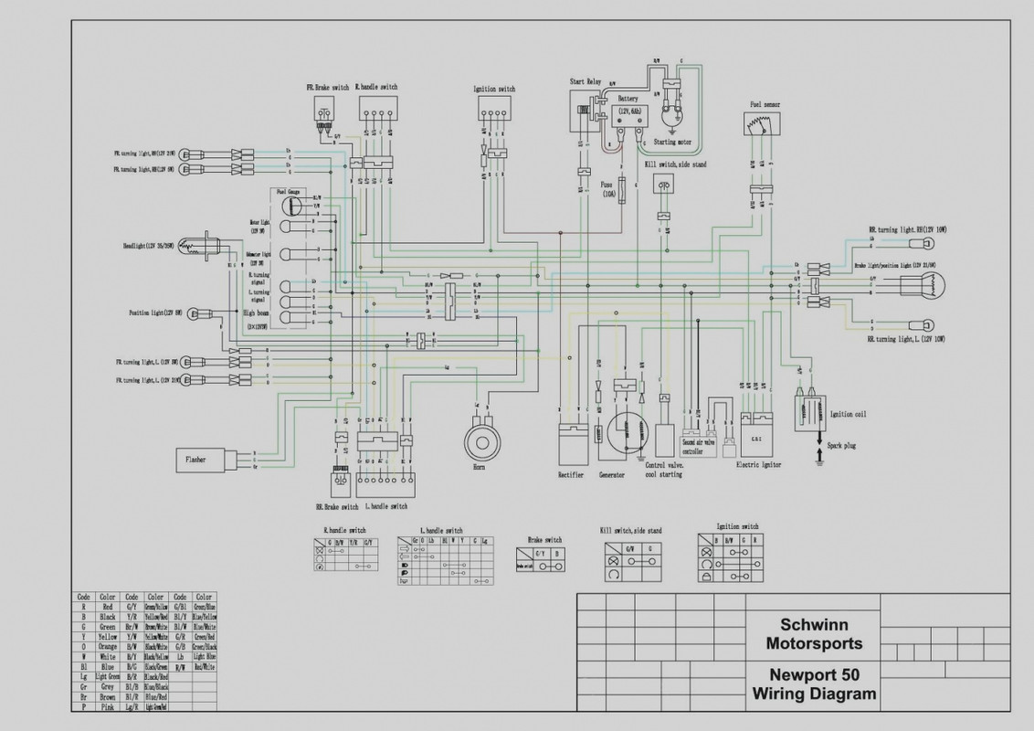
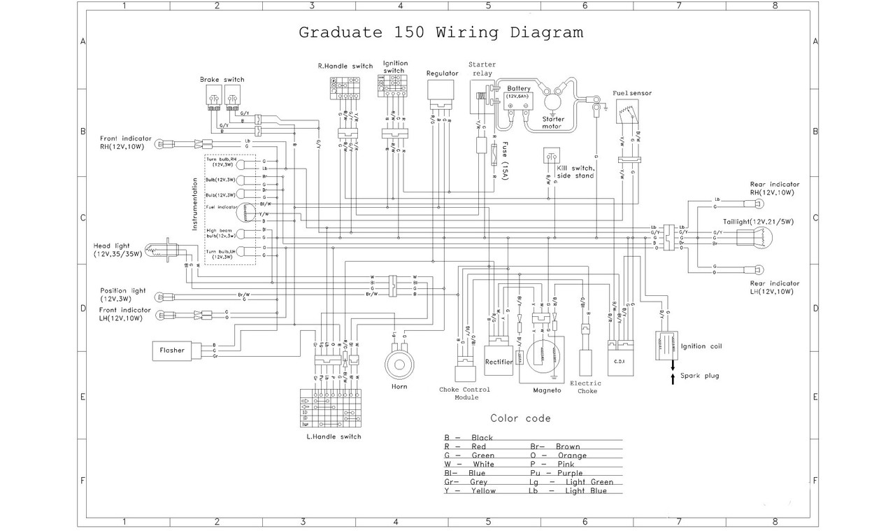
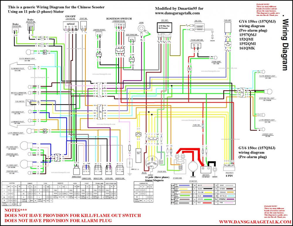
I have not seen a wiring diagram for 'two wires coming off the lighting coils'... got one?
The systems I have seen, at least for plain old 139QMB versions, not Sym or Kym, is a two wire from the stator leading to a regulator/rectifier that is somewhat questionable. One side produces somewhat DC that operates the lights(not headlight) and the gauges and turn signals. The other side, AFAIK, produces AC of somewhat regulated voltage that is used to operate the headlights. As far as I have dug into the systems. The rectifier/regulator must be grounded to the chassis, I think, and it dissipates over-voltage(if there is any) as heat. Again, I think.
I have not gotten into the half-wave/full-wave rectification stuff as I thought there was only one charge output that was being 'rectified/regulated'. If there were two AC outputs from the stator, both legs could be fed to a full-wave to get smoother DC output. With one leg, I think it gets pretty bumpy voltage, though it is sort of DC as it does not reverse.
The problem machine seems to have some sort of crossover that is mucking with the ignition, or possibly turning the stator into an electromagnet that opposes crankshaft rotation or is generating some voltage via crossed wires that is mumbling with the CDI. A possible short in the AC winding that operates the CDI, or a cross feed from another winding to the AC producer to operate the CDI could muck things up.
I would get out the diagram, and meter out all the connections on the stator, separate from the bike wiring to see if there was a problem internal to the stator.
I have thought that the Y/W wires from the stator both went to ground, a common ground, so measuring from Y to W should give the ohms for both windings combined through the common ground. GOing Y>ground and W>ground would give the individual windings resistance. What did I miss with getting two wires coming from the lighting coils? Is there another design that does not use Y/W, and has more wires...? Gotta diagrem? Schematic? Peeksure?
I thought these low-budget things gave little care to producing good solid DC out, and full/half wave rectifiers dual circuit would be way above budget... And now we have pink wires.. not me, so I cannot comment with any experience.
tom
|
|
|
|
Post by snaker on Jan 12, 2023 12:09:43 GMT -5
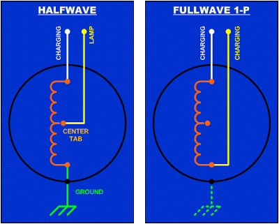
I have not seen a wiring diagram for 'two wires coming off the lighting coils'... got one? The systems I have seen, at least for plain old 139QMB versions, not Sym or Kym, is a two wire from the stator leading to a regulator/rectifier that is somewhat questionable. One side produces somewhat DC that operates the lights(not headlight) and the gauges and turn signals. The other side, AFAIK, produces AC of somewhat regulated voltage that is used to operate the headlights. As far as I have dug into the systems. The rectifier/regulator must be grounded to the chassis, I think, and it dissipates over-voltage(if there is any) as heat. Again, I think. I have not gotten into the half-wave/full-wave rectification stuff as I thought there was only one charge output that was being 'rectified/regulated'. If there were two AC outputs from the stator, both legs could be fed to a full-wave to get smoother DC output. With one leg, I think it gets pretty bumpy voltage, though it is sort of DC as it does not reverse. The problem machine seems to have some sort of crossover that is mucking with the ignition, or possibly turning the stator into an electromagnet that opposes crankshaft rotation or is generating some voltage via crossed wires that is mumbling with the CDI. A possible short in the AC winding that operates the CDI, or a cross feed from another winding to the AC producer to operate the CDI could muck things up. I would get out the diagram, and meter out all the connections on the stator, separate from the bike wiring to see if there was a problem internal to the stator. I have thought that the Y/W wires from the stator both went to ground, a common ground, so measuring from Y to W should give the ohms for both windings combined through the common ground. GOing Y>ground and W>ground would give the individual windings resistance. What did I miss with getting two wires coming from the lighting coils? Is there another design that does not use Y/W, and has more wires...? Gotta diagrem? Schematic? Peeksure? I thought these low-budget things gave little care to producing good solid DC out, and full/half wave rectifiers dual circuit would be way above budget... And now we have pink wires.. not me, so I cannot comment with any experience. tom Lot going on here. Here are some randoms: 1. Half wave/ duel circuit single phase. Ground is involved at the stator White to gnd is high output uses full lighting coil Yellow to gnd is low output uses partial lighting coil  2. Full wave, single phase Not connected to gnd at the stator Both wires are equal legs of one circuit  3. Three phase Most powerful, 3 equal legs of one circuit  |
|
|
|
Post by snaker on Jan 12, 2023 12:17:41 GMT -5
The half wave/dual circuit is typically on a lot of 50cc and had been on many 150cc, although the 150 has been evolving to full wave.
The three phase is deluxe/larger engines only
The dual circuit is setup to supply regulated AC to dedicated headlite plus(low output, usually yellow) with the charging circuit getting regulated and rectified for DC
The half wave incorporates ground at the lighting coil and the RR for the dual circuits
The full wave has no ground at the lighting coil and is only incorporated at the RR
|
|
|
|
Post by snaker on Jan 12, 2023 12:26:48 GMT -5
Here is info on converting from half wave to full wave: I believe that 90GTvert put a post here covering this project. But regardless of which configuration, the RR and stator ALWAYS have to match.  |
|
|
|
Post by GrumpyUnk on Jan 13, 2023 13:39:55 GMT -5
|
|
|
|
Post by snaker on Jan 14, 2023 11:36:14 GMT -5
Yeah, it gets tricky to compare some of this stuff to benchtop electronics, even though its the some electrical theory.
Your half wave link won't open for me.
But that is the simplest.
It can be as simple as a single diode spliced into the output wire from the magneto as many riding lawn mowers have.
Your two full wave links are different designs
One is the typical 4 diode bridge rectifier
The other two diode one is not common and requires a coil center tap for the rectifier ground
That requires a specifically designed coil to provide that
That center tap has to be pretty much exactly in the center of the coil whereas these half wave center taps are not
Say a 6 pole lighting coil stator might have the high output tap at the opposite end of the coil pole (pole 6) from ground and the low output tap might be at pole 5
The other thing is that the half wave stator really isn't a half wave
It utilizing a center tap but is actually wired up as two different circuits using the same coil
|
|
|
|
Post by GrumpyUnk on Jan 15, 2023 16:28:57 GMT -5
Fixed half-wave, extra backslash, and yes, it is SIMPLE.
did not know center-tapped had to be 'opposite' each other(more or less), but make sense for AC input to be a sine wave... would have an AC bump... la dee dah... and then an opposite... and sometime later... another... not real clean power out. Had been thinking the W & Y were more or less a center-tapped and could be harnessed with diodes to be a full-wave...I guess not.
tom
|
|