|
|
Post by 90GTVert on Jul 13, 2020 21:13:16 GMT -5
90GTVert Would you mind snapping the occasional picture of your lathe setup as you are working on a part. It would help people like me that have no clue how to setup for even basic stuff on the mini lathe. I get frustrated every time I get near my lathe. You could post them in your mini lathe thread I'll try to remember. Most of the stuff that I've been doing is shown in videos. |
|
|
|
Post by pitobread on Jul 14, 2020 0:35:58 GMT -5
the tap in the tailstock works well, run a little drag on it and choke up on the tap.
It will run as true as the tailstock is to the headstock!
Is your adjustable? can you center it? is it out?
|
|
|
|
Post by pitobread on Jul 14, 2020 9:17:20 GMT -5
|
|
|
|
Post by 90GTVert on Jul 14, 2020 10:56:10 GMT -5
I actually watched that and others and did some centering earlier. I started by machining a point for the head stock. Had one around somewhere, but couldn't find it. Stuck a dead center and live center in the tail stock and both looked off to the side a little. I did my best to get them to match up with the adjustment on the tail stock. That thing is a pain BTW. I'd get them aligned the best I could and then tighten a screw and it would go out of alignment. I ended up leaving it pretty well snugged and then tapping with a brass hammer to get it where I wanted it and then tightening the screws all the way. Luckily, vertical alignment looked OK to me... cause I don't see any adjustment for that. Guess you'd have to shim it or something if it were an issue.  I center drilled 3/4" aluminum and cut off a few thou. Didn't measure length of cut while doing. Turned out to be 3.4" length of cut and diameter difference of 0.0008" in that distance. That comes out to roughly 0.00024" of taper per inch. In the video, he has 0.13mm over 100mm length. Converted, that comes out to about 0.0013" taper per inch of cut. By that standard, I'm golden. TimNummy is not exactly Joe Pie or Abom or something either, and he's saying roughly 100mm and using a caliper to measure diameters (I used a mic). No offense meant there and I appreciate his vids, just saying. Then I did a quick search and someone quoted a handbook as saying 0.0008" of taper per 12" cut is acceptable. Uhhh. That's 0.00006" taper per inch. I don't think this Chinese mini-lathe is built for that. If I'm wrong and I need to keep at it, lemme know. Either way, the hole that I've been boring and tapping is 0.710" deep. The tap doesn't reach bottom of course with a taper tap, but just say it does. That would be 0.00034" taper across that distance. Now I don't know what it was pre-alignment, but I at least don't think the current alignment would cause me to see huge runout like I have.  |
|
|
|
Post by pitobread on Jul 14, 2020 11:06:13 GMT -5
No, I mean the best way is to turn a lump in the headstock with a taper then use a precision ground test bar in between the centers and dial end to end.
this method is more than close enough, plus on a mini lathe the amount of deflection you would get would make most measurements of such taper pretty hard to control regularly.
However for .0002 per inch that is in not enough to ever loose sleep territory. your trying to make a hole .750" deep, that's like .0001 taper over that distance.
i mean if you were turning a full 10" long diameter, maybe try screwing with it more but you are more than acceptable, in the video it looked like his was .2" out or more. That would definitely screw with everything.
|
|
|
|
Post by 90GTVert on Jul 14, 2020 16:53:28 GMT -5
I took a 1"long piece of round bar and drilled through that. Within .001-.002" from center, based on measuring thickness all around with a caliper. Within 0.001" end to end. I made multiple passes with a boring bar and it didn't really improve, so I guess that means the tailstock drilling is close enough for me.
Re-drilled the other end of one of the pieces that were tapped really wonky. Then I started a tap about as deep as I could with hand turning the lathe. Indicated on the far end, just before the square section. It was way off. I forget the starting figure. Messed with it and got it down to showing about 0.005-0.006" runout as it sat. Hand tapped from there.
Put the freshly cut threads on the crank piece which was chucked in the lathe. Again, that thing has basically 0 runout. Measured across the flats of the hex on the far end and it has 0.014" runout. The same runout that I measured on the tap. I'm not sure that I'm going to get it much better.
BTW, I put all 3 of the new taps in the headstock and spun them. They all wobble.
|
|
|
|
Post by pitobread on Jul 14, 2020 17:33:33 GMT -5
What a great time to learn to thread! Tho internal is definitely more challenging, especially up to a shoulder.
Or get some H2 or H1 CNC taps.
I think you are up against clearance. No matter how much you mess with the tap or alignment you have .005 of clearance + error and its always compounding error. Dumb Luck is the only factor that will get you better than that.
|
|
|
|
Post by 190mech on Jul 14, 2020 18:07:16 GMT -5
I'm scratching my head thinking what applications Ive seen that provided a true running drive to 13+ thousand RPM's from a threaded shaft...None,,   |
|
|
|
Post by pitobread on Jul 14, 2020 18:11:23 GMT -5
Its for sure not ideal using a thread for precision locating. I think it could work, but without getting the pitch diameter damn near perfect it's always gonna wiggle a bit and even "perfect" would still have a bit of runout.
maybe make a mounted spigot that bolts to the face of the MVT rotor?
|
|
|
|
Post by 90GTVert on Jul 14, 2020 21:50:40 GMT -5
I'm probably gonna try to do John's idea (1/4" plate, 5/16" drill rod and M5 set screws showed up today in fact). I was just looking at this as an opportunity to possibly improve or learn something. I guess I may have got the tailstock in better alignment than it was at least. I still kinda wanna try it to see if I could cut crooked threads and end up with a true piece... that won't really run true anyway because threads have clearance.
I went into a store for the first time since March yesterday, to buy a Harbor Freight press. It seems I should have called first. Out of stock there and the other stores sort of nearby. Not sure when it will be back in stock. I got rid of my old one after the jack failed. At that point it had a bad jack and the table was bent. They only sold my 12 ton press as a 6 ton unit after I got it, and I can see why. I didn't even use it that much. Just wasn't worth fixing to me. Figured I could grab one from HF and now I'm gonna try a press fit part with no press. Not that it can't be done, but 0.003" interference fit should be quite snug. There doesn't seem to be any option that comes close to the HF 20 ton press for near the ~$150 that it goes for with a coupon. I thought maybe I could go to $300 if I could find one with a pneumatic function since so many people that get the HF press upgrade to their air hydraulic 20 ton jack and it ends up around $300. Can't seem to touch their price on that either. Not 1 press on local ads when I looked for perhaps a used option.
|
|
|
|
Post by 90GTVert on Jul 15, 2020 22:05:58 GMT -5
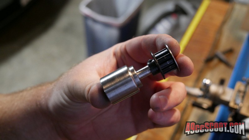
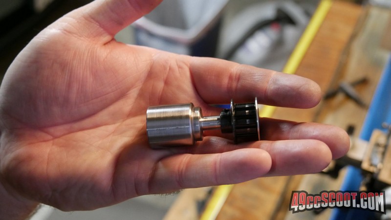
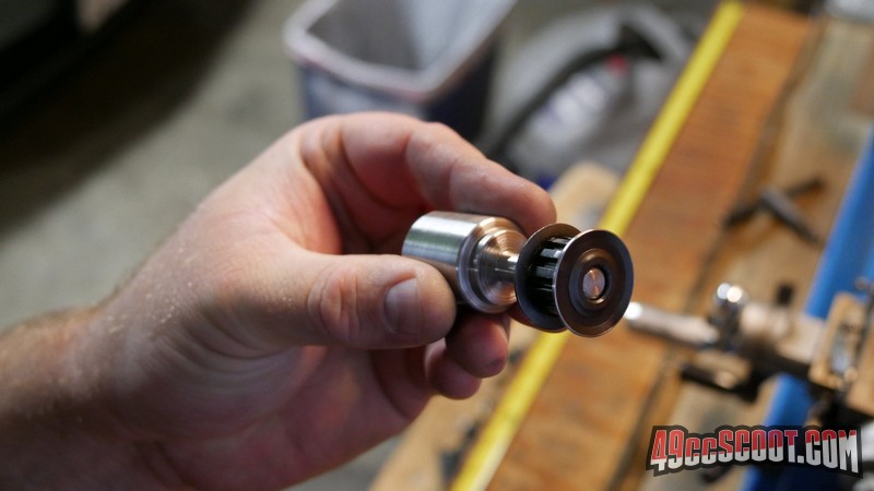
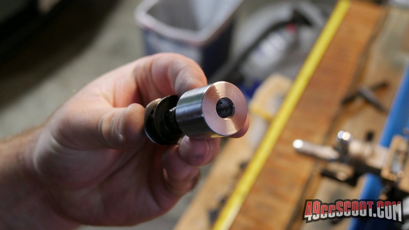
I've got the nut-style pulley adapter mostly finished, I think. I decided to use round bar instead of hex since the hex portion will be off anyway. Drilled. Tapped. Mounted to crank. Crank basically zeroed out. OD machined. Adapter directly in chuck. Checked and tapped back to the near 0 runout that it had while mounted to the crank. Then the rest of the work was done.     So I think all I need to do is try to get a couple of flats on it for a wrench. It may need some trimming. Haven't tried to check it on the crank yet. Won't be able to put a socket on it so it could be torqued. I guess I could cut a hex, but I don't know if it's worth the trouble. I'd guess the easy way would probably be to print a degree wheel and mount it with the piece so it could be indexed for whatever cuts need to be done. You may notice that the pulley is missing some of it's coating. The outer flange was out of round when spun. No way I could put this much effort into trying to learn to create a true piece from a lousy tapping job and leave that, so I quickly cut it round. |
|
|
|
Post by 190mech on Jul 16, 2020 3:50:30 GMT -5
Nice work!!I know this is splitting hairs,as the pump does not create a lot of torque,but the drive direction would be toward loosening so maybe a dab of loctite would be in order during installation?
|
|
|
|
Post by 90GTVert on Jul 16, 2020 6:18:57 GMT -5
Nice work!!I know this is splitting hairs,as the pump does not create a lot of torque,but the drive direction would be toward loosening so maybe a dab of loctite would be in order during installation? I've had the same thought along the way. I kinda think it would slip the belt before it would back off the "nut".. but I still wouldn't trust it without some thread locker. Who knows what will really happen once subjected to load, high RPM and time. |
|
|
|
Post by 90GTVert on Jul 16, 2020 21:39:20 GMT -5
|
|
|
|
Post by pitobread on Jul 17, 2020 8:00:42 GMT -5
Yeah man.
My only thing I think I would have done differently is make it so the shaft would be thicker till it got to the pulley so it could run up against something, but I assume that was done because you don't really know where the pulley has to ride yet.
Other than that you prevailed and learned some useful stuff!
Fun fact, you can use the jaws of the chuck to do indexing for hex, if you make up a bar to rest the flat on the side you have 3 indexes 120 degrees apart, switch it to the other side and you have the 180 flats.
|
|