Post by usmcdoc on Aug 19, 2012 10:08:37 GMT -5
A very common cause of no spark is a defective ignition or kill switch. Before beginning to troubleshoot ignition problems, it is best to bypass the switches.
Bypassing the switches
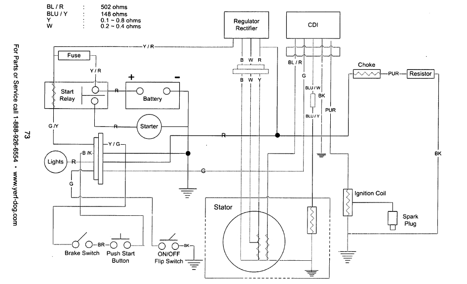
1. Reference this pinout diagram.
2. Create a jumper wire from pin #4 directly to a good grounding spot on the engine.
2. Remove the #5 wire from the CDI plug at the harness. This can be done with a sharp narrow tool like an ice pick or stiff paper clip. Looking from the front of the plug, you will see small metal tabs on each pin which secure them to the plug. Push the tab down and the pin will release. Be careful not to break the plug or pin.
Troubleshooting the Stator:
1. Set your multimeter to read in VOLTS "AC".
2. Locate and disconnect the Black/Red and Blue/Yellow wires coming from the stator, where they plug into the main engine harness. (These are both bullet-style connectors)
3. While cranking the engine, use a multimeter to check for voltage coming from the Red/Black (CDI power wire) and the Blue/Yellow (trigger wire) coming from stator. Place the black lead of multimeter on a metal surface of the engine while using the red lead on the tips of the wires.
4. There should be between 20vAC ~ 100vAC coming from the CDI power wire (Black/Red), although much lower voltages will still be able to produce spark.
5. There should be at least 0.05vAC coming from the trigger wire (Blue/Yellow).
Normal values:
Stator output: 20vAC minimum.
Trigger output: 0.05vAC minimum.
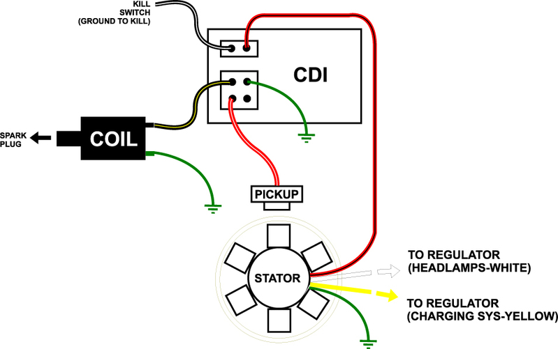
The CDI unit is powered by the AC current coming from the wrapped stator winding. This current is stored in a capacitor within the CDI unit. When a signal is received by the trigger pickup passing over the flywheel magnet, the CDI will discharge the stored energy into the wires leading to the ignition coil.
Troubleshooting the CDI:
1. Ensure your multimeter is set to read in VOLTS "AC".
2. Just like before: while cranking the engine, use a multimeter to check for voltage at the two primary wires of the ignition coil. Connect your back multimeter lead to the black ground wire at the coil, and with the red lead to the lighter color wire (usually blue or purple, but it varies). At this step we are checking to see exactly what the CDI is outputting. Write the voltages down and continue to the next step.
Normal values:
CDI output: Can be 5% to 30% less than the output from the stator. The minimum we have seen working is around 18vAC.

Bypassing the switches
1. Reference this pinout diagram.
2. Create a jumper wire from pin #4 directly to a good grounding spot on the engine.
2. Remove the #5 wire from the CDI plug at the harness. This can be done with a sharp narrow tool like an ice pick or stiff paper clip. Looking from the front of the plug, you will see small metal tabs on each pin which secure them to the plug. Push the tab down and the pin will release. Be careful not to break the plug or pin.
Troubleshooting the Stator:
1. Set your multimeter to read in VOLTS "AC".
2. Locate and disconnect the Black/Red and Blue/Yellow wires coming from the stator, where they plug into the main engine harness. (These are both bullet-style connectors)
3. While cranking the engine, use a multimeter to check for voltage coming from the Red/Black (CDI power wire) and the Blue/Yellow (trigger wire) coming from stator. Place the black lead of multimeter on a metal surface of the engine while using the red lead on the tips of the wires.
4. There should be between 20vAC ~ 100vAC coming from the CDI power wire (Black/Red), although much lower voltages will still be able to produce spark.
5. There should be at least 0.05vAC coming from the trigger wire (Blue/Yellow).
Normal values:
Stator output: 20vAC minimum.
Trigger output: 0.05vAC minimum.
The CDI unit is powered by the AC current coming from the wrapped stator winding. This current is stored in a capacitor within the CDI unit. When a signal is received by the trigger pickup passing over the flywheel magnet, the CDI will discharge the stored energy into the wires leading to the ignition coil.
Troubleshooting the CDI:
1. Ensure your multimeter is set to read in VOLTS "AC".
2. Just like before: while cranking the engine, use a multimeter to check for voltage at the two primary wires of the ignition coil. Connect your back multimeter lead to the black ground wire at the coil, and with the red lead to the lighter color wire (usually blue or purple, but it varies). At this step we are checking to see exactly what the CDI is outputting. Write the voltages down and continue to the next step.
Normal values:
CDI output: Can be 5% to 30% less than the output from the stator. The minimum we have seen working is around 18vAC.