|
|
Post by 90GTVert on Oct 2, 2010 7:08:37 GMT -5
This thread contains parts and pieces of a few 50 to 90cc Minarelli horizontal (1E40QMB) engine builds, compiled to help anyone considering taking on their own 90cc project. I use the term "90cc" somewhat loosely here. What I'm referring to is an engine with a stroke of 42mm or above and a bore of 50mm or above. 48mm stroke and 54mm bore is usually the upper limit for this style of engine. Crankshafts and cylinder kits with strokes and bores larger than those are most likely intended for the Yamaha Aerox, BWS, and Grand Axis 100cc engines which appear to be pretty similar, but parts are not interchangeable. 190mech's 49cc To 103cc Stroker BuildThe case cutting in this build is done with equipment that most of us don't have, but there are lots of details, specs, and pictures helpful to anyone building a 90cc engine. CLICK HERE to skip to it. 90GTVert's First 90cc BuildIn this build, the crankwheels were cut to a smaller diameter so less material would need to be removed from the crankcases. The crankshaft clearance work was done by a machine shop. CLICK HERE to skip to it. 90GTVert's Detailed 90cc Case PrepThis is the most picture and detail intensive of the build segments in this thread. It is also the most tutorial-like. CLICK HERE to skip to it. 90GTVert's Case Cutting ToolA homemade tool design that cuts the crankshaft area of the cases. Full specs and template included, but you will need a lathe to reproduce the tool. CLICK HERE to skip to it. Oldgeek's Case Cutting ToolsHomemade tools for cutting the crank area and the cylinder area of Minarelli cases to accept large bores and strokes. CLICK HERE to skip to it. 190mech's Dual Purpose Case CutterA homemade tool that cuts both the crank and cylinder area of Minarelli cases. CLICK HERE to skip to it. |
|
|
|
Post by 190mech on Oct 5, 2010 4:11:04 GMT -5
190mech's 49cc To 103cc Stroker BuildThis is a condensed version of some parts of 190mech's CPI engine build. For the full thread, CLICK HERE.
I finally decided to start a project I've wanted to do for a while. A 50cc scoot with a 100cc engine,geared so it will cruise at 60 without turning a million RPM.I ordered a NCY 54mm cylinder kit for a 90cc engine,have a 45mm stroker crank on the way. Cases must be cut to fit both the larger cylinder and crankshaft. Got the engine off and mostly apart; 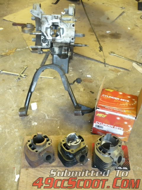 Here is the 50cc,70cc,and 54mm(103cc with stroker crank)cylinders; 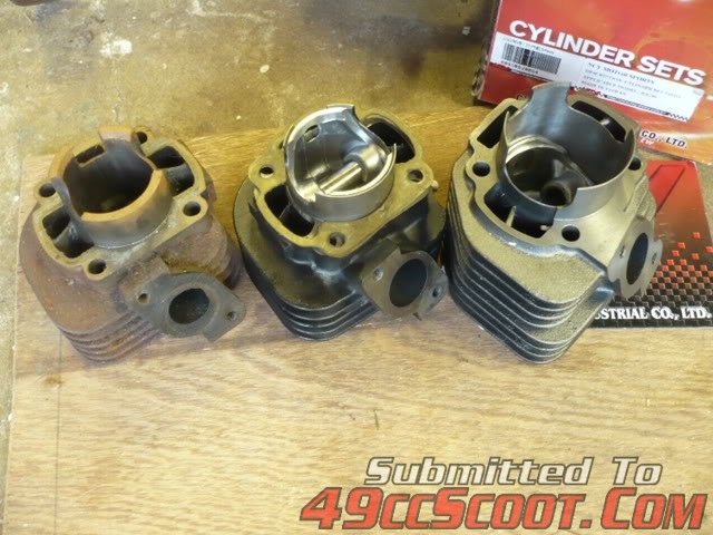 This is how much metal must be removed for the cylinder to fit the case; 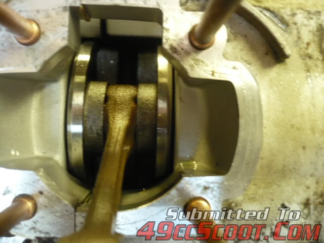
Got some time to 'make chips' today.Setup the cases in the mill to cut the cylinder mouth; 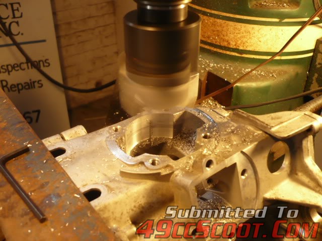 After many chips,here is what it looks like; 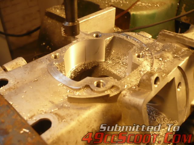 Here is the cylinder test fit,Whew,it fit! 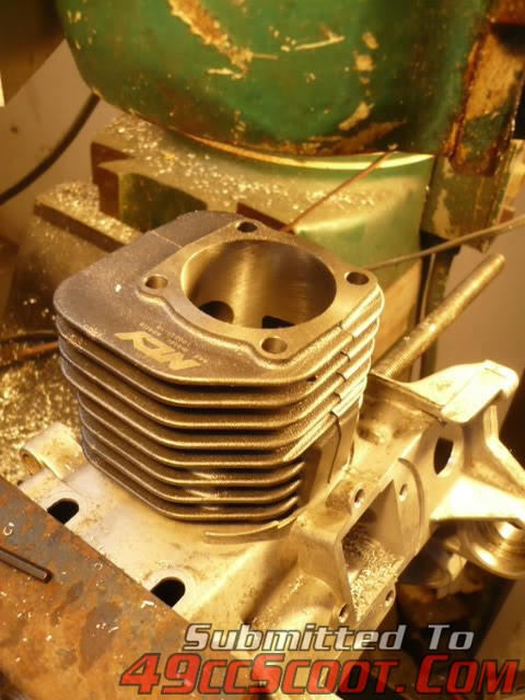 Started roughing out the transfer tunnels; 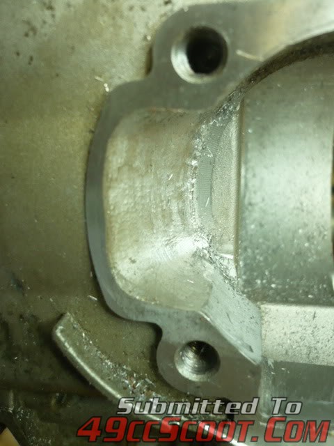 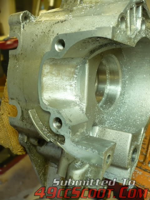 Here is the cylinder in the case,ya'll think that web under the boost port needs to be cut straight down? 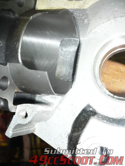 I have a 'stuffer' crank ordered,so that should keep the primary compression up.. Might cut a little more on that case channel,but worry about the bolt hole and case support there.Ive also seen where guys are cutting a 'scallop' out of the rear cylinder skirt to aid in boost flow.Like this; 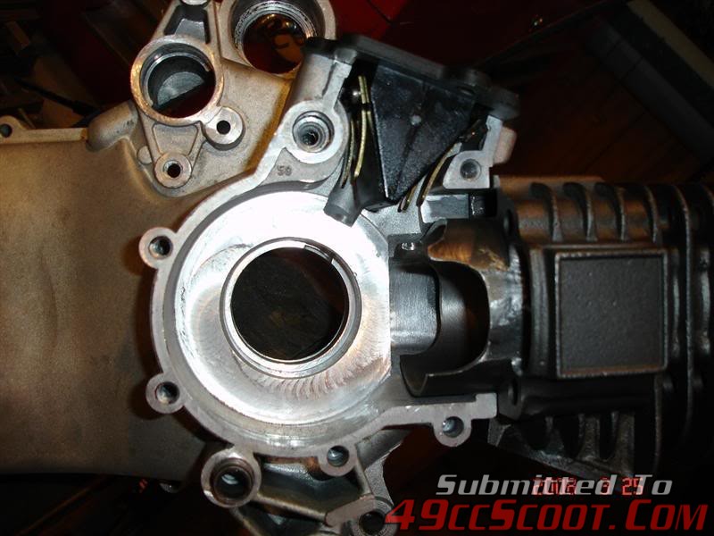 The 50cc case appears to be restrictive in these areas for proper cylinder filling and I think some time spent here will make a stronger running engine..
Crank arrived today; 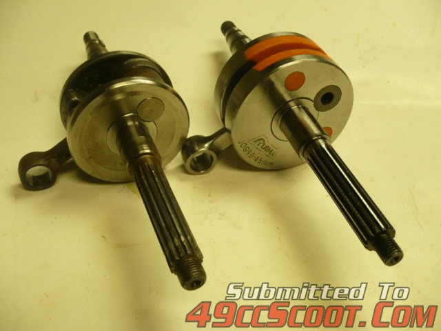 Stock shaft 72mm ,new shaft 78.2mm,stock case 73.5mm,, 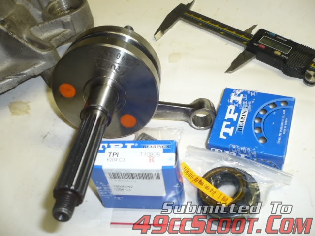 |
|
|
|
Post by 190mech on Oct 5, 2010 9:14:24 GMT -5
Said the heck with all my night work and got back on the "103"! Cut the crankcases to fit the 45mm stroker shaft,final cut size is 79.9mm; 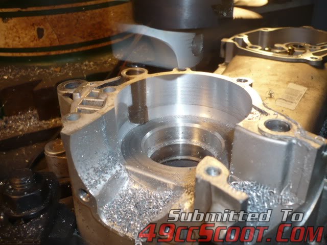 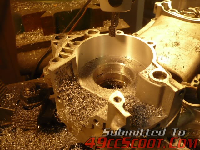 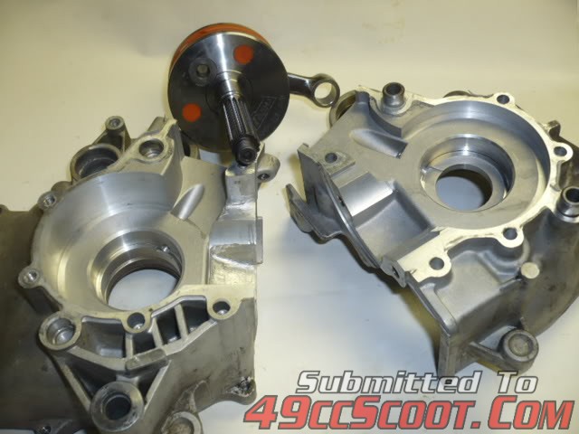 Downloaded pics that Wax posted elsewhere and started roughing out his 'trench cut' mod; 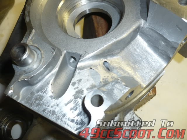
Did a rough and quick port timing check tonight,looks like this NCY cylinder was made for a 42mm stroke..Exhaust duration is 182 degrees,transfer duration is 134 degrees,boost duration is 130 degrees,piston is about 1mm out of the bore at TDC...Will post more after I think about these numbers a while....
After a think session and rechecking the port timings,I'll cut 1mm from the cylinder base,should put me at 130 transfer,then the exhaust will be cut to 183-185,maybe widened a bit too.
Everyday is not a good day...After working 2 ten hour days this weekend I decided to do some '103' work tonight..Knew the port timing was off,chucked it in the lathe to cut 1mm off the base; 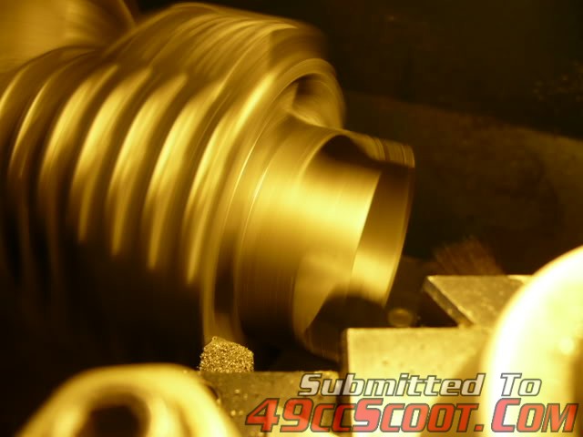 All went well,base cut nicely; 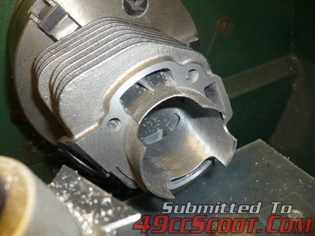 Took the cyl home to make another check,DARN!I figured the wrong way!Now I need to make an aluminum spacer to cover my mistake and get the timings right..Spacer fab builds real good arm muscles   I was sleeping when I did my math!Needed more duration,not less on the transfers,this must be a very mild cylinder.Gonna try a .090" spacer and see what that gives.
Fabed a .090" spacer,with 1 gasket(.037"),I got 134 transfer and 184 exhaust,think I'll make one from .062" or maybe .050" with 2 gaskets and see what that gives me..
Had a little time after work tonight to make a .050" cyl base spacer,with a .015" gasket on the top side and the stock gasket below,my transfer timing is now 130 degrees(right where I wanted it!),raised and widened the exhaust port to get 184 degrees |
|
|
|
Post by 190mech on Oct 6, 2010 9:19:34 GMT -5
Here are some pics of the 103 project,cyl to case fit; 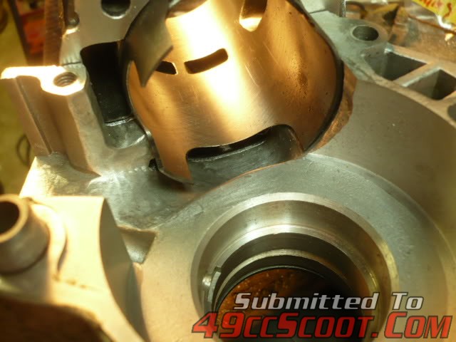 BDC view of case to cyl fit; 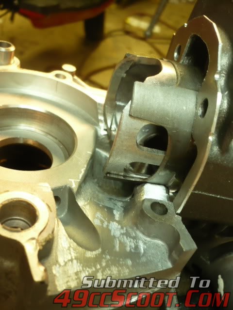 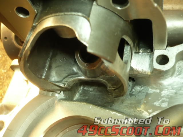 Piston at TDC; 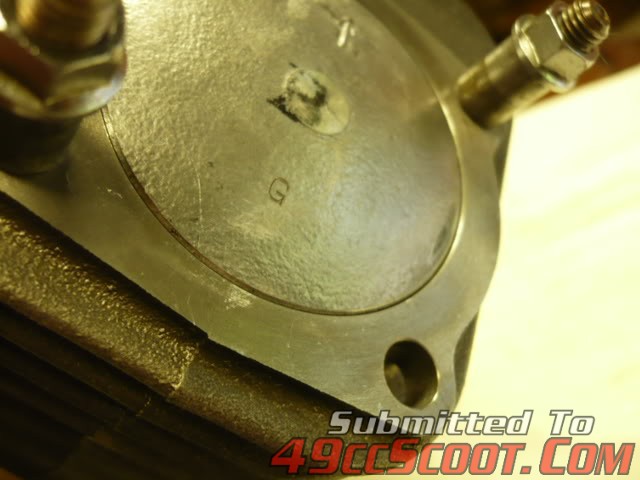 Squish check with head gasket; 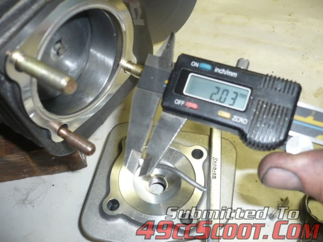 Ex port after cutting; 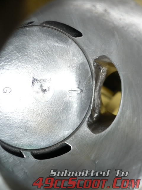 View of intake side of cyl skirt after cutting; 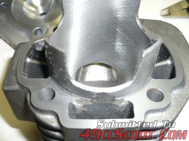
Got the cases together today,what a bear!Fabed a 'puller' to install the crank without hammering(affects balance) or excessive heat(dont wanna melt that epoxy!),verrry snug fit..Made up a reed spacer to get it away from the boost port,used .250" aluminum; 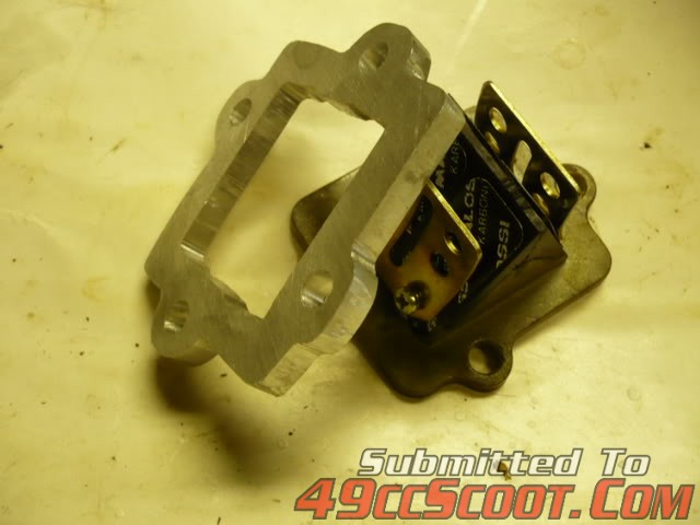 Did a pressure leak test,had a big one at the carb/reed adapter, cut a gasket and it still leaked!This seems to be a common problem; 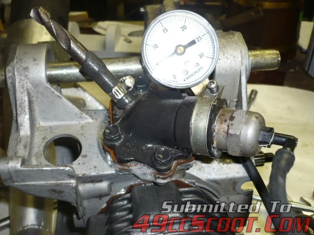 Cleaned it up and put a coat of BBQ black on for heat dissipation; 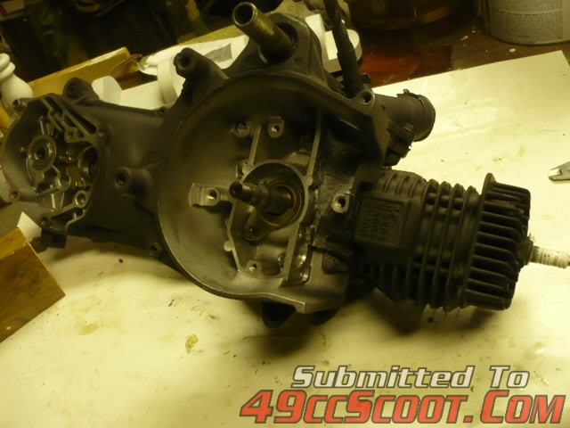 |
|
|
|
Post by 90GTVert on Oct 16, 2014 12:33:59 GMT -5
90GTVert's First 90cc BuildThis is a condensed version of some parts of T1's build thread. For the full thread, CLICK HERE.Stock 39.2mm stroke crankshaft on left, full circle 45mm stroke crank on right. 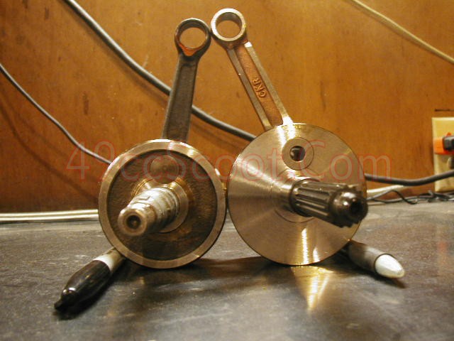 I'd like to get the cases to my machinist soon, but I can't just drop them off and say "make 'em bigger." I used a set of dummy bearings (stock bearings that I sanded to allow them to slide over the crank and into the cases without pressing or heating and cooling) to install the stock crank into each case half. I used feeler gauges to get an idea of the stock clearance between the crankcase and the crankshaft. I came up with 1.2 - 1.3mm.   After checking that way, I measured the crankshaft and the cases with calipers. I got about 74.25mm for the ID of the crankcases and 71.75mm for the OD of the crankshaft. That makes 2.50mm total or 1.25mm of clearance on each side. That coincides with what I came up with initially. My stroker crankshaft measures 78.25mm OD. Add 2.50mm to that to get 1.25mm of clearance all around and I should need my cases to be bored to 80.75mm. I'm thinking maybe I should cut it back to around 80mm. 80.75mm is gonna be so close to the bolt holes. 80mm would give me 0.875mm all around. 80.25mm would give me 1mm all around. 80.75mm (actually 80.74, I got tired of trying to get that .01mm dialed in)   80mm   If the cases look like too much meat might be removed,how about taking a MM or 2 off of the crank wheels,just a thought...
I dropped off the cases, the crankshaft, my dummy bearings for test fits, both my 2T flywheels, and my Sunl's flywheel to the machinist. The flywheels are there for lightening, no work needed for the build. I told him that ideally the crankcase would be taken to 78mm diameter and the crankshaft would be reduced to 76mm. He said he'd look it all over and see what he felt safe with.
I was working in the garage last night when my machinist popped his head in and said my parts were finished. ;D He lightened one flywheel, knocked a bit off of the crank, and opened up the cases. The bill was a bit steeper than I expected, but it was 6 hours of labor total and he billed me $240. Machining the cases alone should be around $125-150. The cases were opened up to about 79mm I.D..  They still have a decent amount of meat left around the threads.  The crankshaft was machined down to about 76.75mm O.D..  He got as close to the pin as he felt safe.  Nice to see the crank actually fitting inside the cases with just a touch over 1mm all around.  Still only able to fit a stock or 70cc cylinder and piston, but the bottom end is ready.  |
|
|
|
Post by 90GTVert on Oct 16, 2014 16:47:54 GMT -5
90GTVert's Detailed 90cc Case PrepI've got a 200 mile engine from a 2008 Vento Triton GT5 that I was planning to leave alone. Maybe I'd just want a stock type engine one day. Prob not though, so it's not getting left alone. Here's the engine at 7PM. 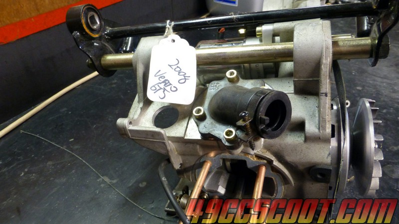 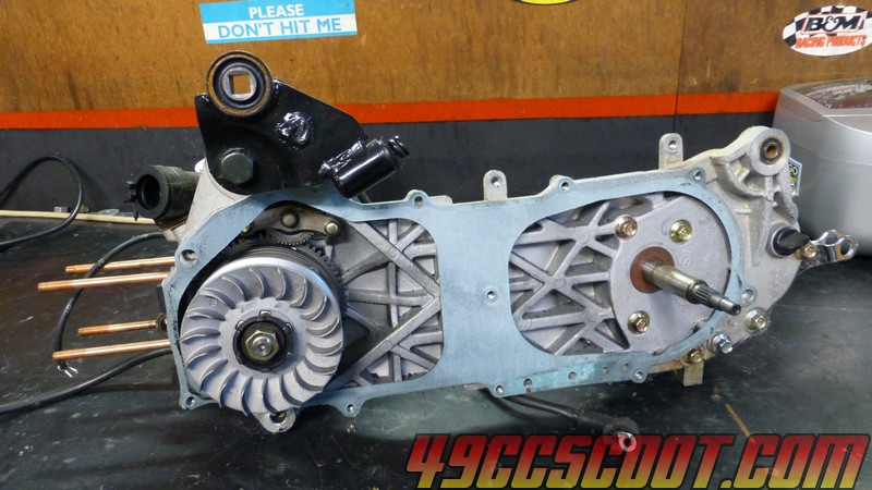 Not too much later... 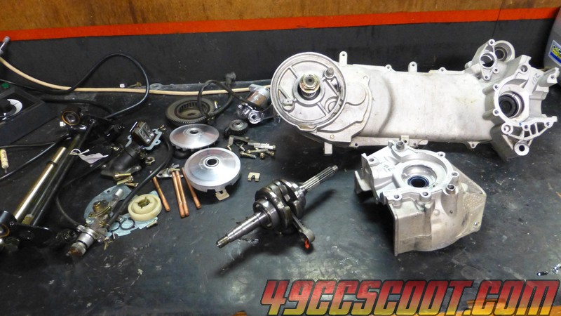 Stock crank and 45mm stroker crank. 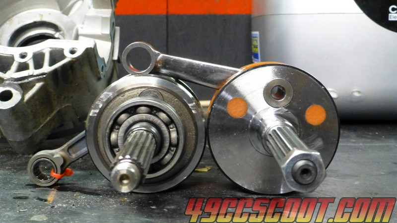 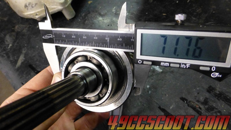 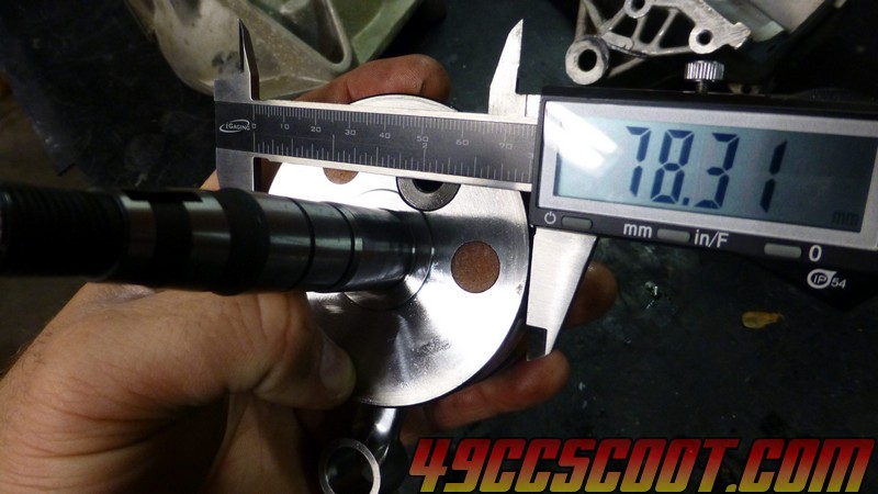 I stuck dummy bearings in the cases so I could put the crank in and mark around it so I'd have a guideline for cutting. 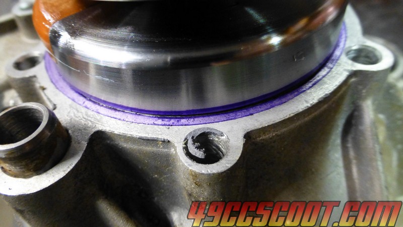 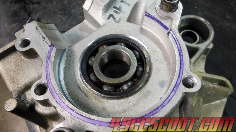 It's a little tougher on the big half since the crank cant reach the bearing so you have to do your best to center it before marking. 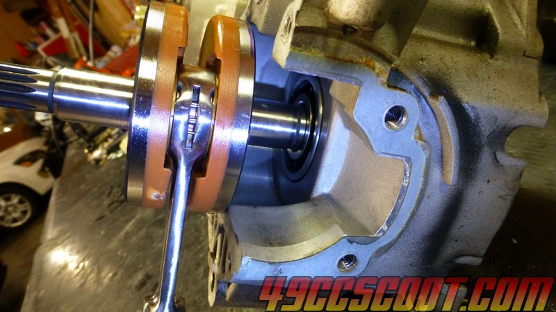 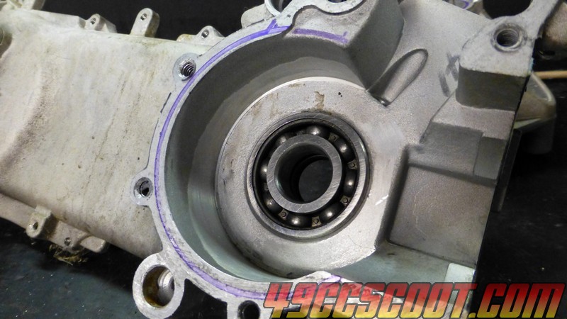 I loaded a carbide cutter into the Foredom rotary tool. Dremel and similar rotary tools work fine. You can also use cutters and other accessories with 1/4" shanks in a die grinder, drill, etc... I would suggest using something that you find easy to control. Larger and more powerful tools are capable of removing material very quickly. While this sounds like a good thing, it can also get you into predicaments very quickly. Longer bits may make the job of opening up the large case half go easier, but 1/8" shank rotary tools probably won't have enough torque to use them properly. 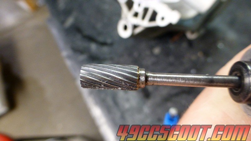 Be sure to use a flat end like the first pic below, not the cutter end like the second. The flat end will dig into the cases bad enough and many spots are not very thick. Small holes can often be repaired with JB Weld, but obviously it's best to try not to break through at all. 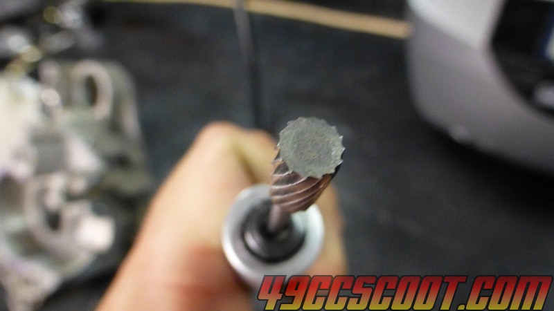 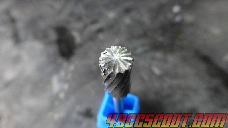 After about 5 minutes... 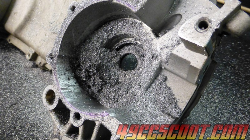 Another 15 minutes later... 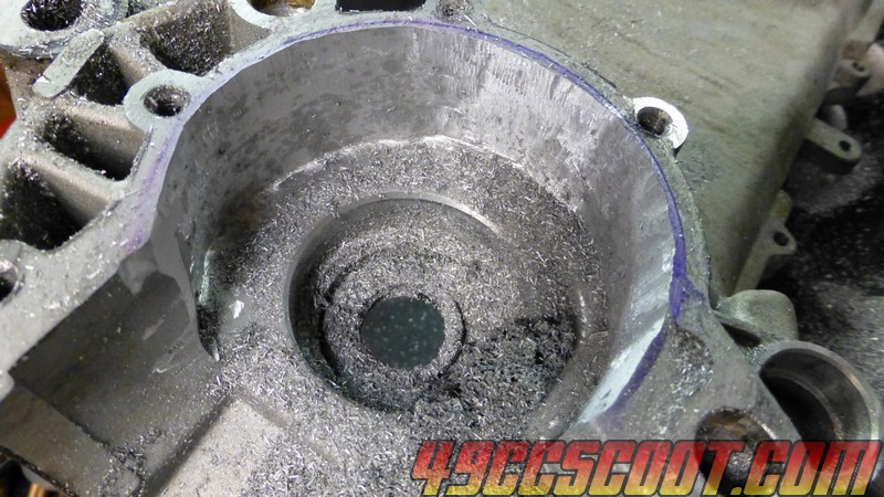 That was as far as I decided to go with the carbide cutter. I knew I had room left, but I wanted to finish up with flap wheels so they'd smooth out the cases more. I use 60-120 grit wheels. 60-80 to start out and 120 if you desire a little smoother finish. I find that flap wheels tend to wear down on the corners, which makes getting a 90 degree intersection of the case walls and sides where the bearings sit. Pick up spare flap wheels if you want to use them for all of the finish work. 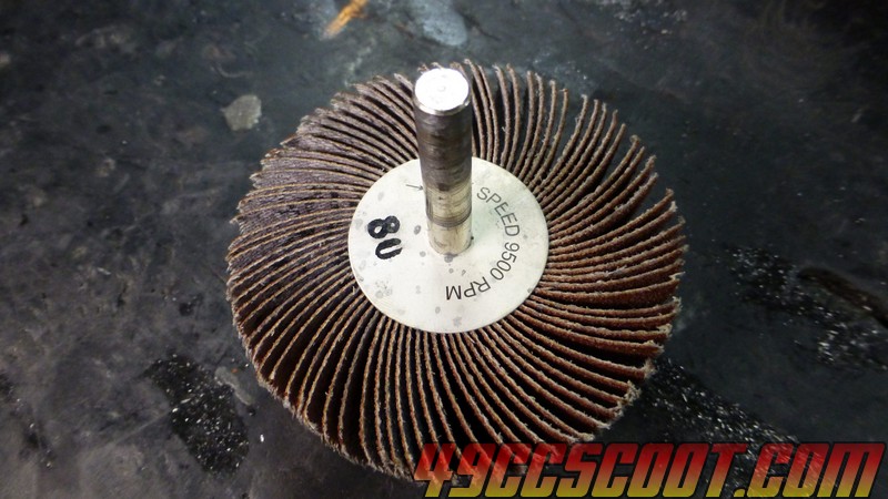 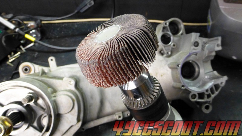 I worked it over for quite a while with the flap wheels. Had to switch back to the carbide burr to knock out some material right at the bottom edge that is tough to get with the wheels, especially after they wear a little and don't have a sharp corner. Somehow managed to break the carbide cutter. I apply pressure on it, but nothing I would have expected to snap it. Oh well. It was long enough to work still. 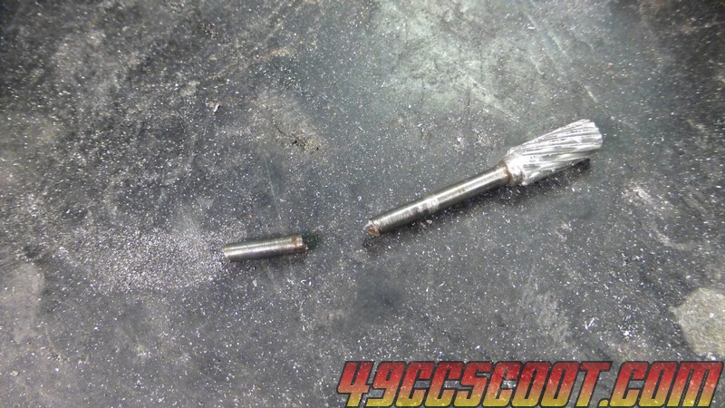 Eventually I got it finished up so the crank fit. Before calling it done I put the crank in multiple times, looked at clearances, cut, repeated till I was satisfied with it. Not exactly pretty, but it'll work. 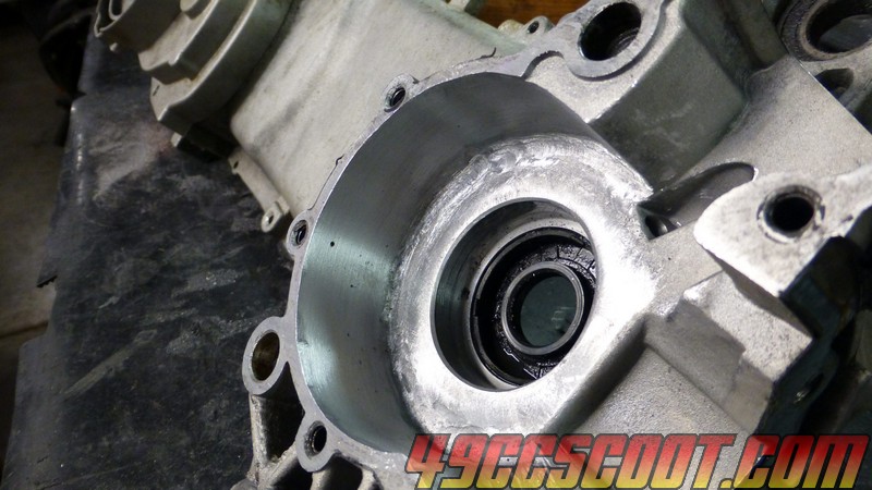 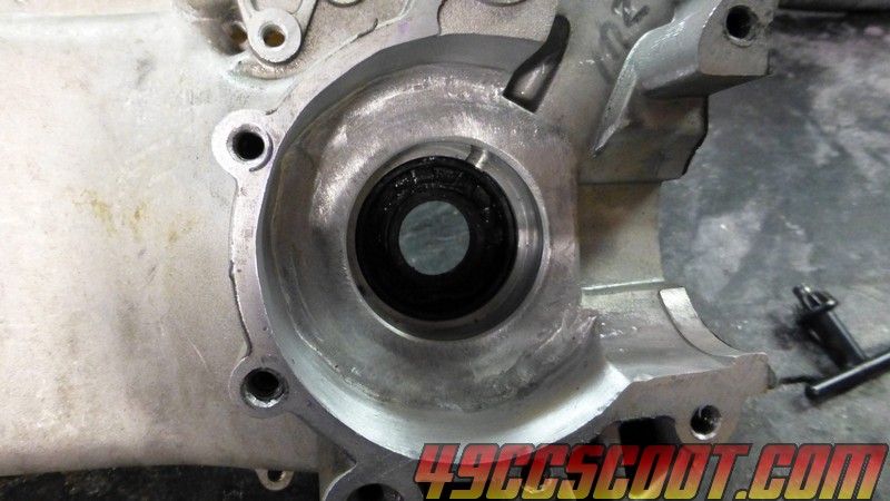  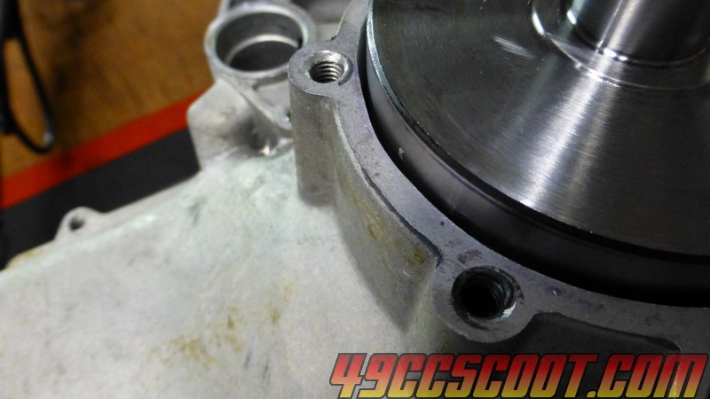 I really should have used the carbide burr longer to begin with. It removes material way faster than the flap wheels and the job would have been much faster. The slow removal toward the end does make it easier, at least to me, to get a more smooth result. By this time it was approaching 10PM. I wanted to get the small half cut, but I opted to quit with the power tools. |
|
|
|
Post by 90GTVert on Oct 16, 2014 17:05:52 GMT -5
I switched over to the small case half and started out with the carbide cutter. I went closer to the edge with the cutter this time to save time with the flap wheels. 15 minutes later it was rough, but the crank would fit in there. 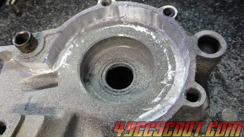 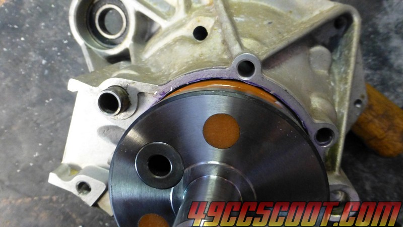 I used the flap wheel to smooth it out better. After a couple of checks the crank fit with a much more even gap all the way around it. Maybe 5 mins with the flap wheel. 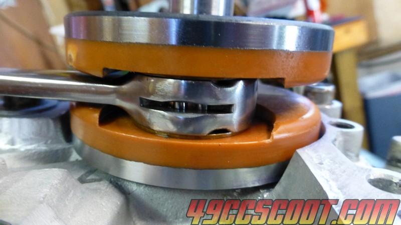 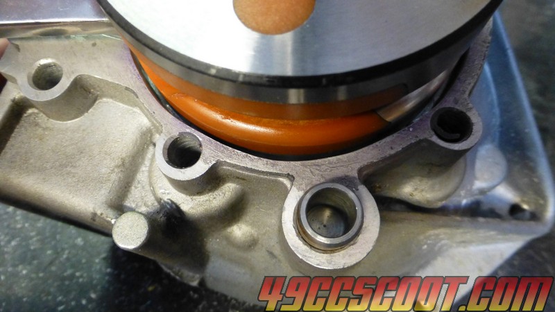 Overall it took about 30 minutes to finish the small half. Going deeper with the cutter saves a lot of time. I ended up with a little more clearance on this half by the time it was smoothed over, so I think maybe not going as far as this time, but farther than last time, with the cutter would be a safe bet. It will depend how smooth you are with the cutter I suppose. Before you assume you are finished with crank clearance on both case halves, I suggest installing the crankshaft with dummy/mock-up bearings. Install and tighten the case bolts and make sure the crank still moves freely. If it doesn't, first make sure the crank is not sitting all the way to one side or the other of the cases. If the crank still won't move easily, you will need to take it apart and carefully inspect it to find where your clearance issues are. Next, I wanted to make clearance for a 54mm bore cylinder. I bolted the case halves together and installed the studs. 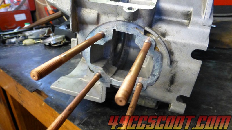 I used a base spacer that I cut to match the cylinder as a template to mark the cases for cylinder clearance and port matching. You could also put the cylinder over the studs and mark around the skirts, but I think having a gasket or spacer that matches is easiest for marking the ports. 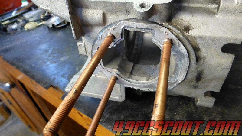 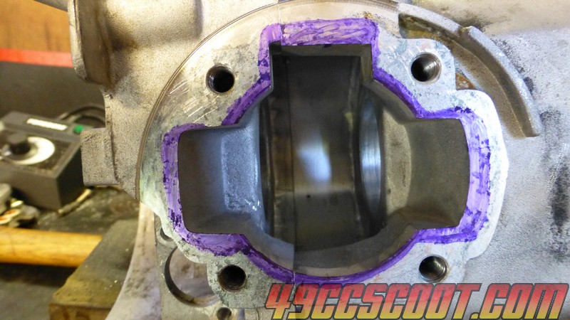 At least this case has a little more meat between the transfer matched to the cylinder and the edge than some. If you find that there is much less than 2mm of material left outside of the ports, consider cutting the cases slightly smaller. Here are notes from 190mech on the topic : Case to cylinder duct matching was explored by world class tuner Jan Thiel on the Aprillia RSA125 and he found no power loss with miss matches of several MM's,even with base gaskets hanging in the ducts!Its all about duct volume which we DONT have in scoots..Perhaps some J-B weld to build up outside the case flange for the base gasket to sit on will "get it to the end of the season" like my crop duster buddies say...Prep the case with coarse sand paper,lube the cylinder base,slather on J-B to the case,then set and tighten the lubed cylinder on the case.. 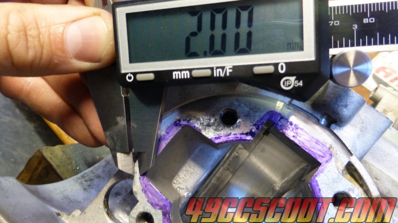 I separated the cases and removed the studs. Then I marked guidelines for making cylinder clearance down into the cases with a marker and ruler. 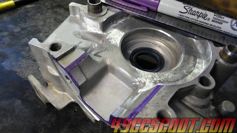 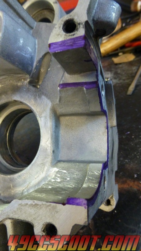 Before you start cutting, it would be a good idea to mask off the cases on the sealing surface past where you wish to remove material. Sometimes the bit slips on edges and can mar the sealing surface. If the bit you use and your machine is reversible, you can also do that if the bit wants to slip/take off on certain edges. I did not initially do this, and put a few scratches on case mating surface, but luckily nothing major. 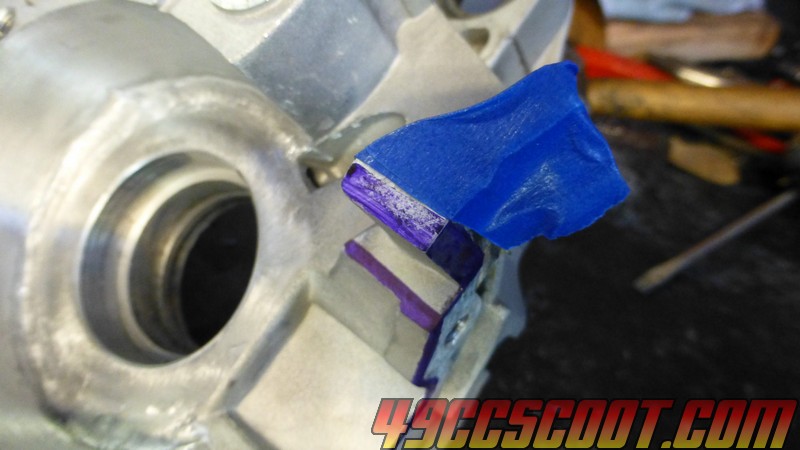 Within about 30 minutes with the carbide cutter, I got the cases cut down in the cylinder skirt areas by my marks. 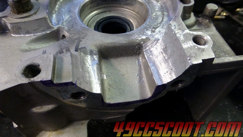 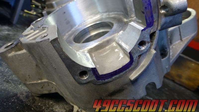 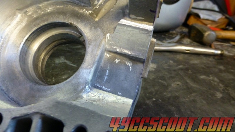 I put studs into each case half. 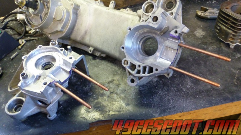 Then I could slide the cylinder onto the studs on each half and check for clearance problems. 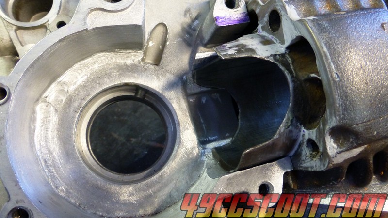 Once I saw that both case halves allowed the cylinder to fit all the way down, I put the cases together and verified that the cylinder still slid tight up against the cases. 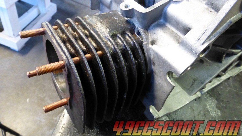 *Note : I'm only noting some times because people have asked in the past how long it takes to do some of this stuff. At this point I'd say you could probably get the crank and cylinder to fit the way I have in anywhere between 3-6hrs. That's a huge gap I guess, but everyone will work a little different and different tools. The more checks you make as you go, the more time you'll spend. If you're a badass with badass tools, you could prob do it in even less time. If you're really new to all of it and new to this sort of work, it could take far longer. The real answer I would prefer to give is... you should not build a stroker if you are in a time crunch of any sort. Also keep in mind this is only to the point that the crank and cylinder fit onto the cases. The cases still have 50cc ports, no trenches, etc... A very long way from being complete. Even once it all fits together and ports match up, you still have to deal with all sorts of issues with timing and clearances with the cylinder, piston, head, and gaskets that sometimes go easily and sometimes turn into tons of work. Maybe you can build a stroker from scratch in a day or two, maybe it'll give you headaches for weeks. If you want closer to a bolt-on and go, stick with stock stroke 50-70cc stuff.* *Note : I'm only noting some times because people have asked in the past how long it takes to do some of this stuff. At this point I'd say you could probably get the crank and cylinder to fit the way I have in anywhere between 3-6hrs. That's a huge gap I guess, but everyone will work a little different and different tools. The more checks you make as you go, the more time you'll spend. If you're a badass with badass tools, you could prob do it in even less time. If you're really new to all of it and new to this sort of work, it could take far longer. The real answer I would prefer to give is... you should not build a stroker if you are in a time crunch of any sort. Also keep in mind this is only to the point that the crank and cylinder fit onto the cases. The cases still have 50cc ports, no trenches, etc... A very long way from being complete. Even once it all fits together and ports match up, you still have to deal with all sorts of issues with timing and clearances with the cylinder, piston, head, and gaskets that sometimes go easily and sometimes turn into tons of work. Maybe you can build a stroker from scratch in a day or two, maybe it'll give you headaches for weeks. If you want closer to a bolt-on and go, stick with stock stroke 50-70cc stuff.* |
|
|
|
Post by 90GTVert on Oct 16, 2014 20:38:23 GMT -5
Next I started to work on matching the ports. 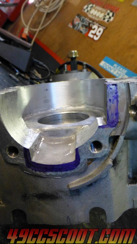 I was using the straight cylindrical carbide cutter and going deep. I don't know if I went temporarily (I hope) brain dead or what the heck I was (or wasn't) thinking, but I was cutting the thing like I had a solid block of billet in front of me. 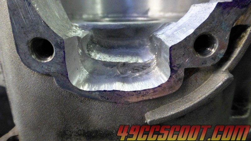 After cutting the first big chunk, I just went on to match behind it. That's a terrible idea. These cases aren't that thick, and I know that, so the inevitable happened and I broke through. 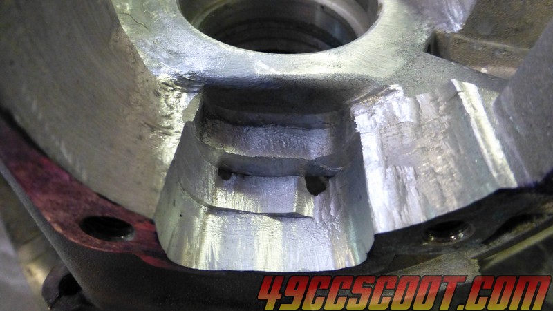 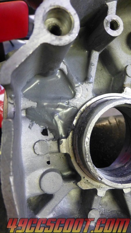 Normally what I do is use a conical burr and that makes blending from the largest section where the cylinder meets up and down into the cases quick and easy. I can't blame the bit though, I've cut enough cases to know better. At that point I decided to go with it and cut sort of a stair step, breaking through a little more. I figured I might as well go with the deep transfer at that point. It would need filling anyway, so I can either try to make it more like normal or go with a deep tunnel there. 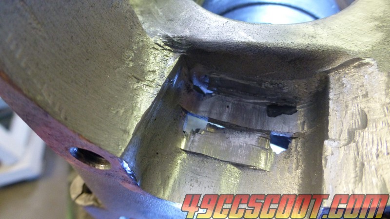 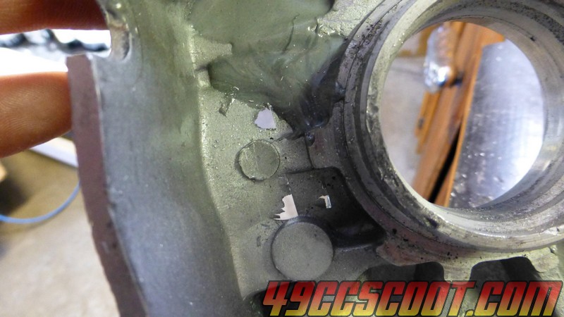 Then I moved on to matching the boost port. That can be cut straight in. I managed to break the carbide burr for a second time. This time it snapped where it's of no use. While I don't feel I'm putting so much pressure on the thing that it should snap, I think the fact that the Foredom does not die down like every Dremel I've had when you put pressure on it is not helping me. If you've ever heard people talk about powerful tools getting them in trouble, well I think this is an example. A rotary tool with less power prevents getting too frisky, because when you apply pressure the power isn't there and RPM drops a lot. You don't have much choice but to back off. Not so sure this would happen with better bits, but these things aren't made to take out 2-3mm per pass at any high rate of push speed/force regardless. 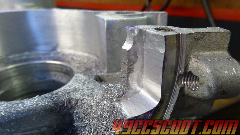 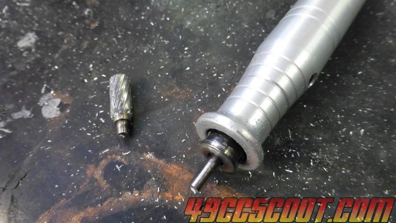 I switched over the the other cylinder with a cutting end to finish up most of the cut. 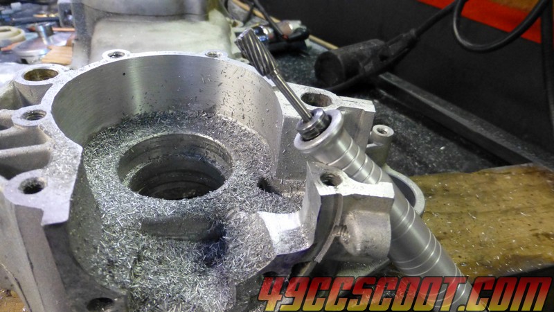 Then I used a file for a flat boost port roof. 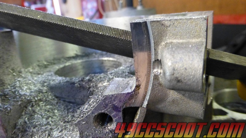 Then I turned my attention to the small case half. 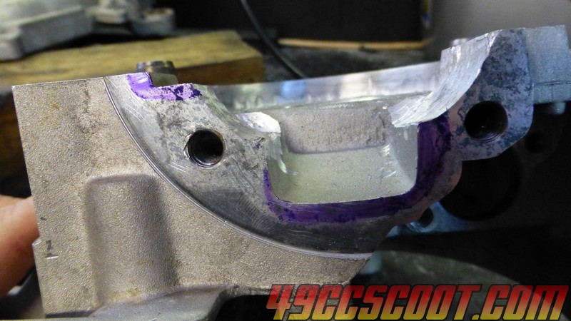 This time I switched to a cone shaped burr and blending the port took a matter of a few minutes with no crazy breakthroughs involved. I think this shape would be more beneficial that some giant ledge anyway. I'm not gonna cut huge trenches so the big area would prob just end up as a dead spot and do more harm than good. So if you're checking this out as a guide, this is the way to do it. 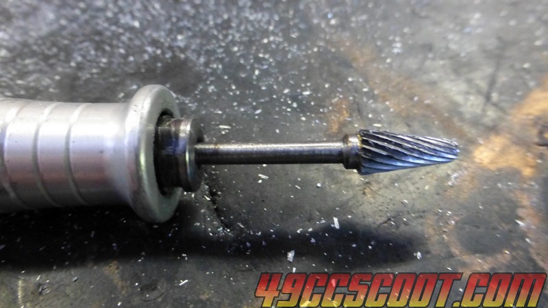 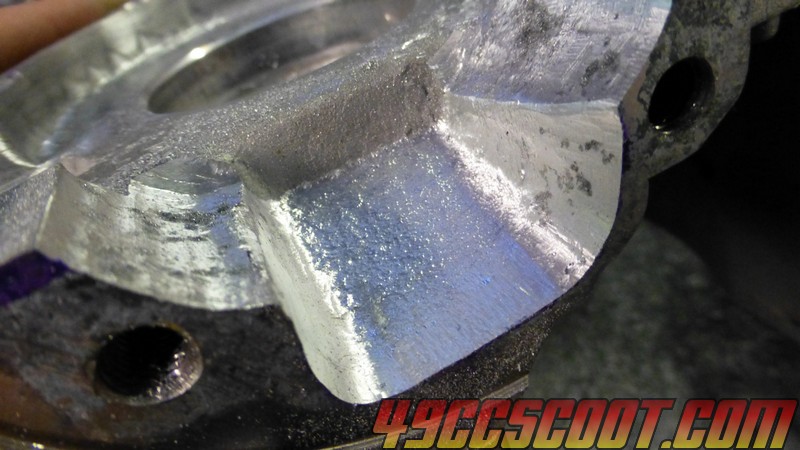 Boost port cut in with the cylindrical cutter. 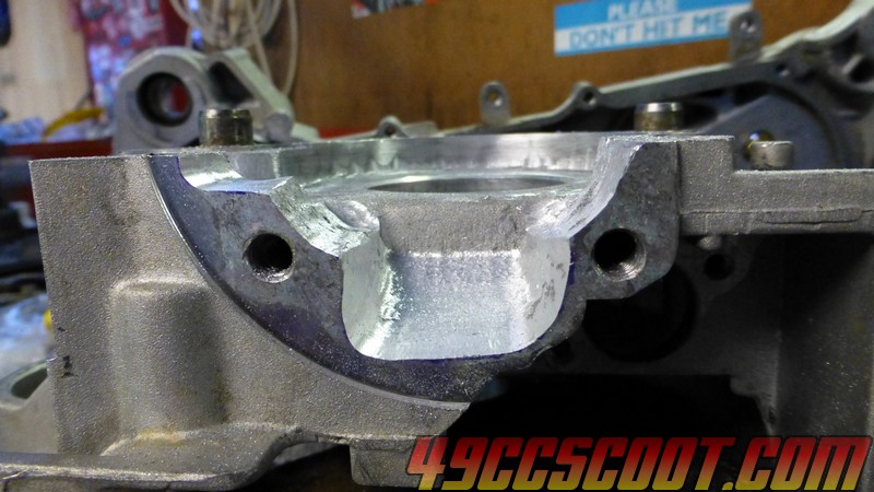 With the cutting done, for now, I focused on filling my screw-up. I knocked out the super thin sections attached to the holes first. You will notice that there is already JB Weld on the cases. This is for a trench cut case porting mod that is described in another thread. 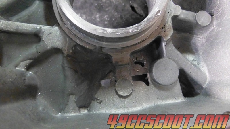 Then I put a few layers of Gorilla Tape on the inside of the cases too stop the JB Weld from flowing freely. 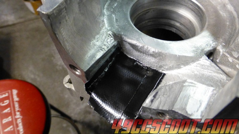 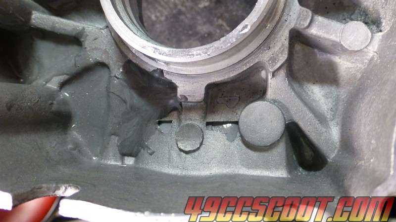 Filled the CVT side with JB. Hopefully after this cures for a bit I can remove the tape and apply JB from the inside that I can attempt to shape later. We shall see. 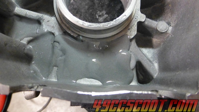 The JB that was applied to the CVT side of the large half had cured enough by the next morning that I could take off the tape and work with it. 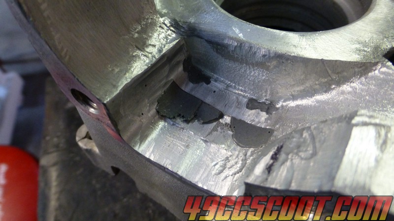 I propped the case up so it's about as level as I can get it side to side, but the front/crankcase is just slightly elevated above the rear. Hopefully that way the JB will settle in where I need it. If it stays like it is, I shouldn't have to do much to blend it in and have something reasonable. I'm sure for the best results it could use more applications and lots of blending, but I'll be fine with it as long as it's secure and somewhere near a sane shape. 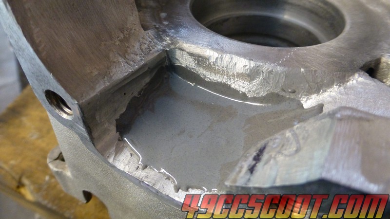 The JB Weld was dry enough to work with by night, so I sanded it a bit. I didn't blend it in to paper thin edges. Thought it may be best to leave a little more material so it hopefully is less likely to flake off. 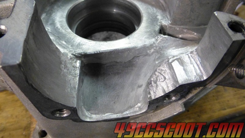 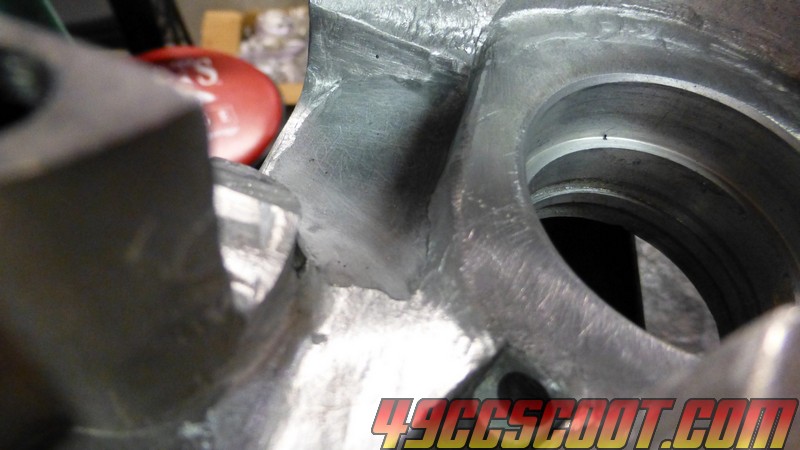 At that point the cases were ready to accept the stroker crank and cylinder with matching ports. 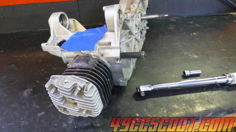 |
|
|
|
Post by 90GTVert on Sept 10, 2017 10:05:03 GMT -5
90GTVert's Case Cutting ToolPics of the tool : 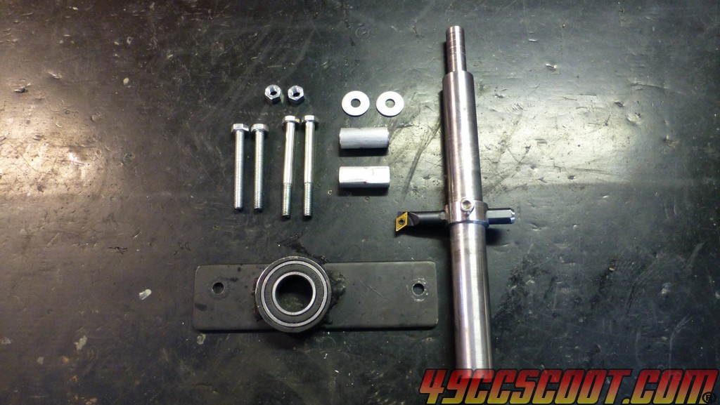   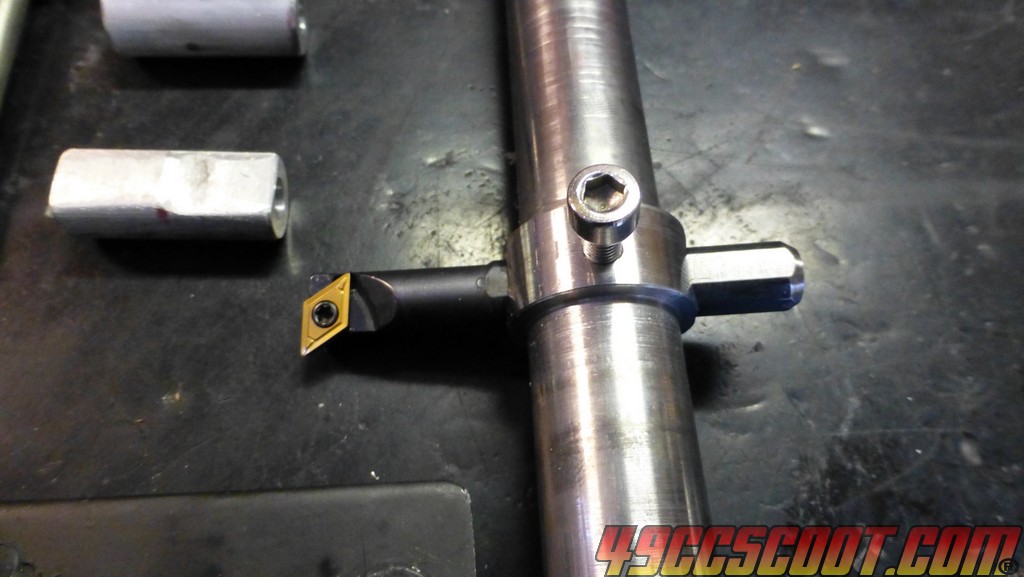 Here's a video showing the tool in action and telling about why it's needed, plus some general 90cc info. Here is a sort of "blueprint" of most parts of the tool. Click to get it full size. 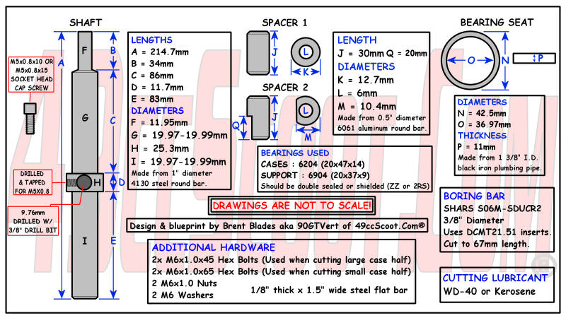 There is wiggle room in some of those measurements. - Spec F on the shaft could be cut however needed to fit your drill's chuck (1/2", 3/8", etc...). - Spec D is basically just cutting close to the hole for the boring bar so you get plenty of travel. A big lip below the boring bar hole wouldn't let you reach the bottom of the cases. Put a straight cut there, not a chamfer, again to maximize travel. - You may want to start large and do some test fitting for G until the feel is right. Don't get it too snug or it won't want to move well once it's in 2 bearings. Too loose and you get more wobble in the cutter. - The bearing seat says it's made from 1 3/8" black iron plumbing pipe. Not sure if that's accurate, but it measured just over 35mm ID and it's plumbing pipe that I got from a local hardware store long ago. Here's the template for the support plate. Click the image to get the pdf so it's easy to print in actual size and make sure nothing is trying to resize it before you print. Check scale by comparing to the ruler printed with the template. This is what the 1/8" thick by 1.5" wide steel flat bar is for. The hole for the shaft may be smaller that you want, but the important part is that it's a starting point on center. Definitely check all fit before you go transferring it onto steel. 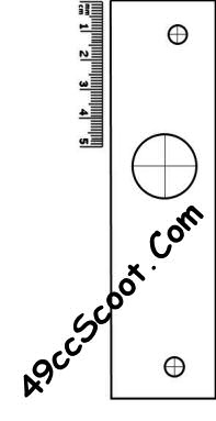 Just in case there's any issue with the template, I took a few pics today to show you how it's done so you can make your own. Start off with a piece of poster board or something similar. I used a piece of an old folder, cut to about 1.5" wide and around 5.5" long. 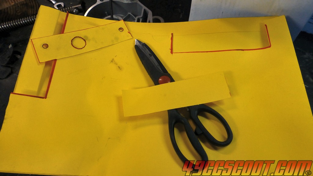 Lay that across the case and try to get it so it's centered over the bearing in the case where the shaft will be. Then mark where the holes in the case are by pressing on the template material. You can use a small hammer and light tapping if you can't get a good mark just pressing with your fingers. You could also try a rubbing with a pencil. Whatever you do, make sure the paper is kept taut as you work. Slack will mess up the spacing. 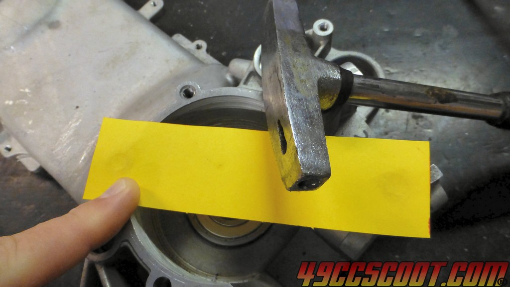 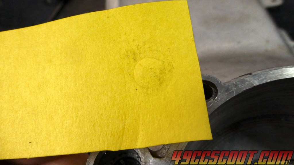 A hole punch is about the right size and the easiest way to knock out those holes. Take your time to get the alignment correct. 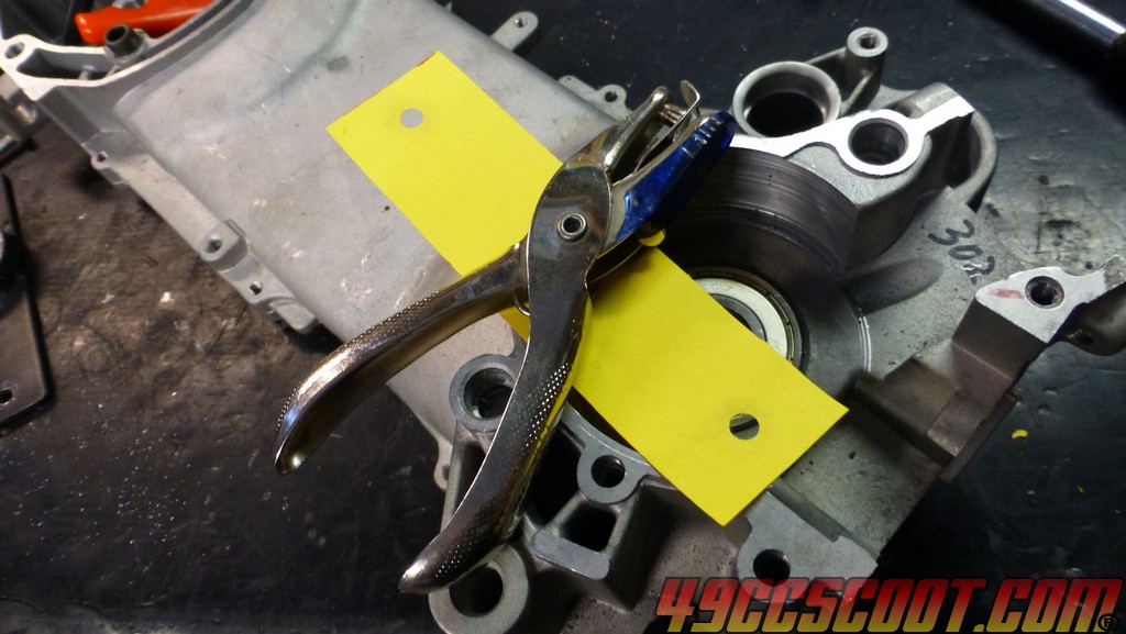 Check the alignment of the template to the holes. If they aren't spot on, redo the template till you get it just right. If all is well, bolt the template to the case, preferably using large washers to spread the load out and keep the material from tearing. 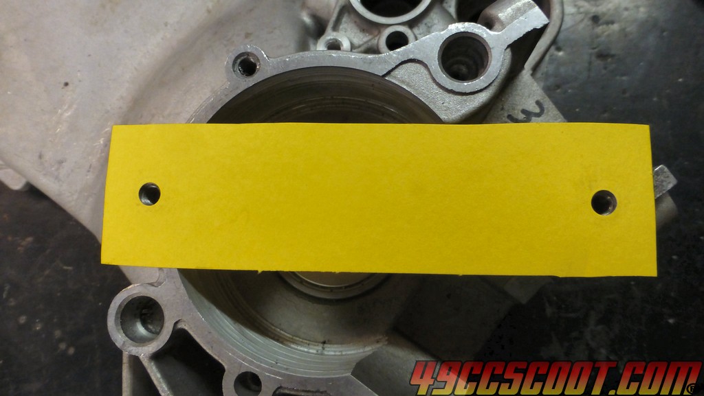 Then slide the shaft up through the bearing and press/tap so you can see it's position. Remove the template and you can cut that hole out or mark for the center of the hole and just poke through there to apply a center drilling point to your template. The hole will need to be larger than the shaft anyway. I went larger than the 1" boring bar section with mine. If you don't get the shaft near the center of the template, start over from the beginning. Something like the quick example that I did would not be good. It doesn't leave much material by the time you drill it out. Put your time into working with poster board so it's easy once you get to making it from steel. 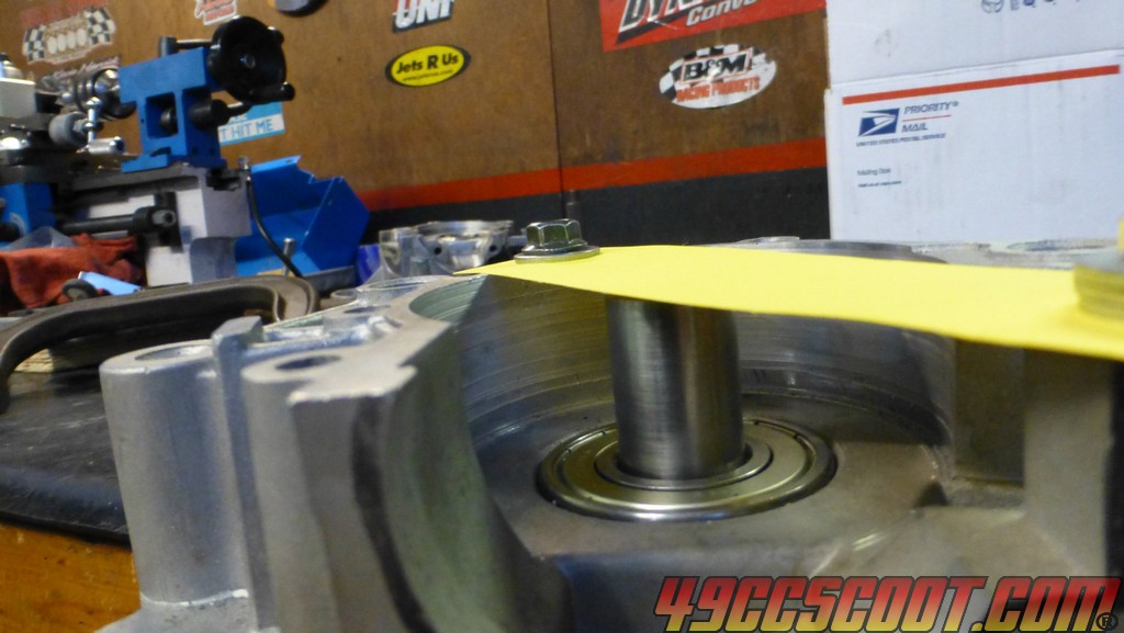 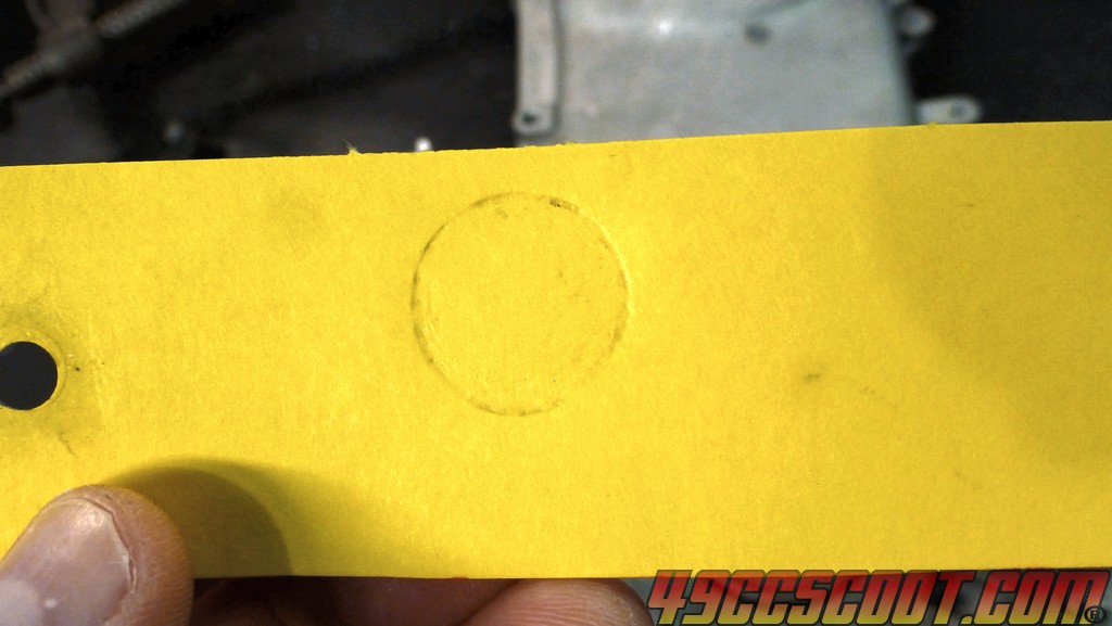 You can find more pics and talk about the tool HERE. Case boring tool here : 49ccscoot.proboards.com/thread/21292/case-boring-minarelli-139qmb-engines |
|
|
|
Post by 90GTVert on Sept 10, 2017 10:50:31 GMT -5
Oldgeeks's Case Cutting ToolsThe final tweak on my rig was a bigger rotary tool (1/4") and cutter. It made a huge difference in ease of operation and I cut the crank area on two sets of cases in less than an hour each. Old rotary tool 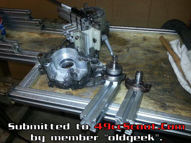 This picture shows the larger rotary tool. 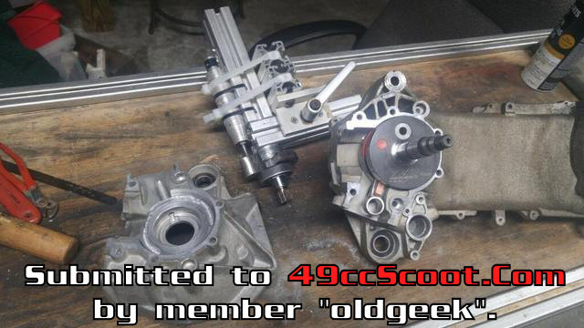 The original posts about building this tool are HERE. I have been working on a method to open up the throat for larger cylinders. Most people just chuck a cutter in a drill and go at it. That is fine, but that is just not the way I want to do it. A couple failed attempts with other jigs brought me to this method using a template and router for opening the throat. It works well and is actually pretty easy to use. However it is not easy making the template with the tools I have on hand. Getting the 52mm and cylinder stud holes cut cleanly in the plate and correctly centered was a chore. Sorry for the lack of decent pictures, I was trying to make a video but it didn't work out. The plate acts as a guide for the cutter to ride against. One pass was made with template in place then the template was removed and the cutting was finished free hand using the first cut as a guide. The last thing left to do to the cases is to trench them so they can flow better. I dont think a tool can be made for that, it all has to be done freehand. 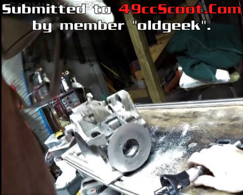 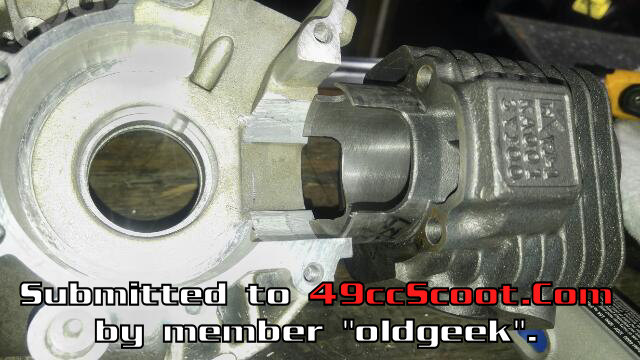 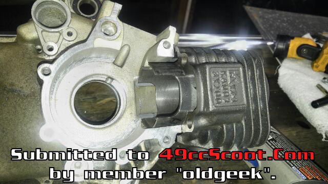 The original posts about this cutter are HERE.
|
|
|
|
Post by 190mech on Dec 27, 2018 19:42:50 GMT -5
|
|