|
|
Post by 190mech on Mar 8, 2024 17:40:55 GMT -5
I think a .002" slip fit is good, if the nut is made from good steel it should ride well on the inner bearing race..
|
|
|
|
Post by 90GTVert on Mar 8, 2024 19:01:58 GMT -5
I think a .002" slip fit is good, if the nut is made from good steel it should ride well on the inner bearing race.. I got 4140 hardened hex rod. Hoping I don't regret getting hardened. I think every other time I've ordered regular 4140 for custom flywheel nuts and such. I figured this would live a rougher life than those. |
|
|
|
Post by 90GTVert on Mar 10, 2024 23:28:38 GMT -5
I've been working on the homemade torsen arm a bit. I went with 1/2" OD tube. I was going to buy 6' of 0.083" wall thickness, but 6' makes shipping high so I switched to 2 3' pieces. I got one 0.083" wall and one 0.065" wall, thinking I can use the thicker tube for two main legs of the arm, then use the thinner for reinforcement. Maybe save a tiny amount of weight and a couple bucks, and also leaves a little thicker tube to weld to a bearing housing and case mounts. The bearing is a 6204-2RS.


I started by using some 1" rod to make a couple of pieces for bolting the arm to the engine. I cut a little indentation in the back of each that's about 0.050" larger than the exhaust mounts on the engine to maybe help locate them a bit, while leaving play. I was also thinking that it pushes them inward a touch, and if spacing is an issue I could cut them deeper later.   Then I started working on the chunk of 2.5" OD by 1" thick steel that I bought to turn into a bearing holder. I would have preferred a pipe or tube, but I couldn't find anything at a reasonable price that met my requirements for size. The steel disc was less than $10. I cut it down to 55mm OD by 23mm thick. That left plenty of material for a back wall, thick sidewalls, and I was going to put a retaining clip groove in on the wheel side.  I spent quite a bit of time trying to set the compound rest at 0° accurately so I could bore a straight hole. I got a dial indicator to read 0 against the shaft of a tool post as I moved the slide, so that's as good as I know how to get it. Even then, the indicator shows deflection as I crank the dial. I set everything up as tight as I could get away with. Cross slide movement was firm and tough to move, and the compound slide was much easier, but snug. I can't just crank the carriage in since it should be straight, because it has all sorts of weird play. I lock it down for any operation that requires much precision.  The bearing is 1.8504" OD. I looked it up and found an absolute max interference fit of 0.00185" and some recommendations around 0.0007". I was hoping to hit somewhere between 0.0007" and 0.001", but I knew it would not bore straight. It never does, even with the indicated 0 across travel. I think there's still deflection or something. I even kept it to 0.005" to occasional 0.010" boring passes to reduce stress in hope of limiting deflection or whatever flex happens. I wound up with 1.8495" ID as near the back wall of the housing as a dial bore indicator fits, with about 0.0015" of taper to the outer edge of the housing. Certainly not ideal, but the actual area where the bearing sits should be pretty much within spec. Again, I don't know how to cut it any straighter on this thing unless I had a reamer just for it or something. So, the bearing can be pushed into the housing by hand a bit, but it stops way before it should. It stops about where it's outermost edge will be, so I think it will be fine.  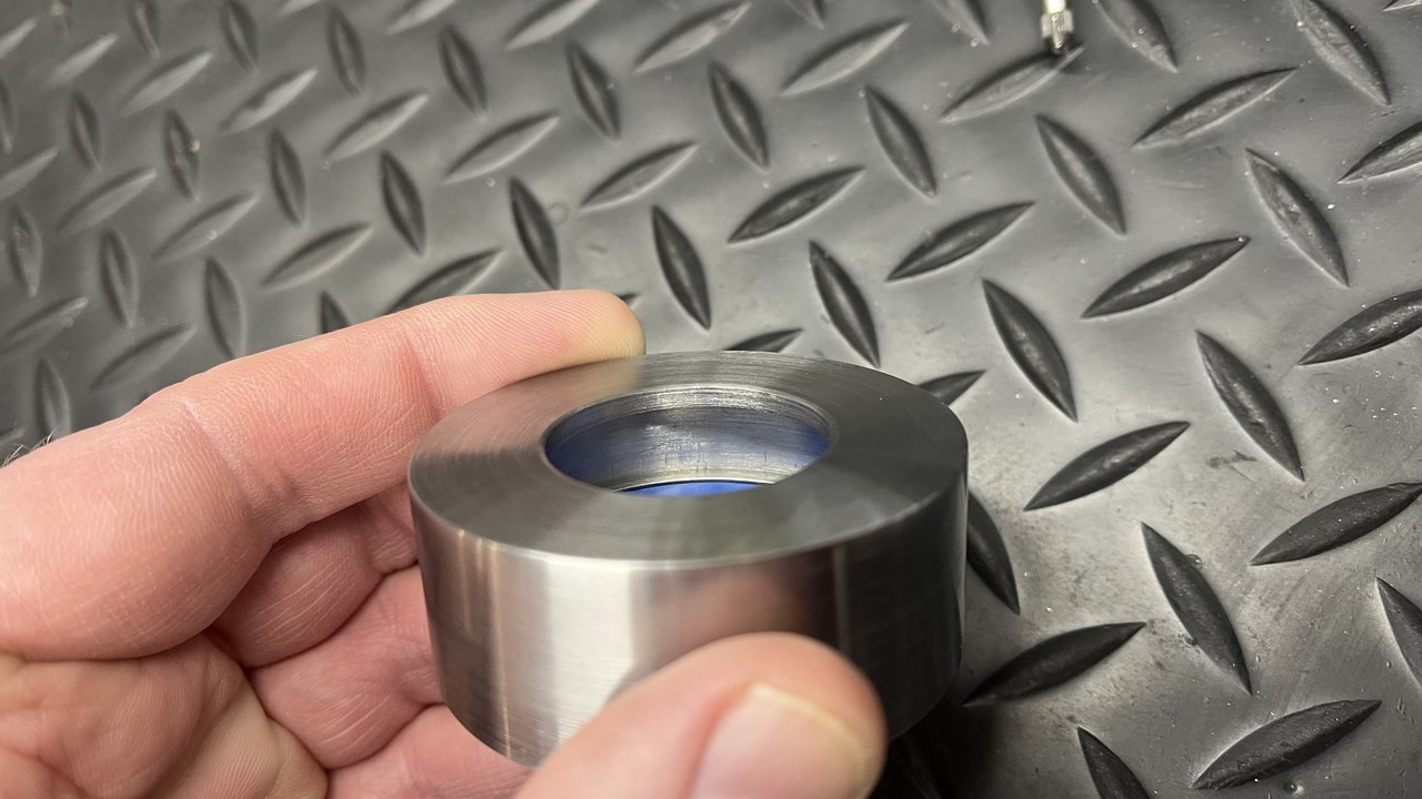
I was planning on putting a retaining clip groove above the bearing, basically just because I've seen other torsens using one. Now I think I'm going to cut the housing thinner instead, leaving more room if it needs to sit closer to the wheel. That's all I've got so far, but that much has taken a long time. All I did today in the garage was bore for the bearing and that took a chunk of the day. I was shocked when someone came and asked if I was planning to eat dinner anytime soon because I had no idea that I had spent that much time in front of the lathe. ~1.85" takes a while when you're cutting 0.010" total off most passes and then checking a lot with a dial bore and micrometer toward the end to be sure it's going how it should. Hopefully it'll all be worth it in the end if I can wind up with a heavier and I'm sure otherwise inferior part and save $20 for just many days of labor. lol Speaking of ordering things... I've contacted ScooterTuning about the piston. Sites are saying April now for expected date. I was initially told it would take 2-3 weeks of delay, but that was the beginning of January. I'm hoping that April date is if you ordered one now. If it is supposed to be April, I'll need to try to get one elsewhere. I've got too much to sort out before the car show in May and TN in June to wait till April for a piston and a new ignition that I may need to figure out mounting for and then still the carb tuning problems. Plus, now the guys that I've been riding with occasionally are asking me when the 2T is gonna be back. BTW, last ride there was a police chase. Not me, but one of the group. I didn't get to see it. I was out front racing a hopped up GY6 with the TMAX and though the cop was coming after us for that. Apparently one of the guys back farther decided not to stop and got away. Wish I got it on camera, but I was so far out front screwing around that I didn't know what was happening for sure, let alone get anything on the GoPro. |
|
|
|
Post by Lucass2T on Mar 11, 2024 3:11:29 GMT -5
Looking good so far!
Any ideas on the color or the arm? Or are you going to put clear over it?
|
|
|
|
Post by 90GTVert on Mar 11, 2024 9:37:47 GMT -5
Looking good so far! Any ideas on the color or the arm? Or are you going to put clear over it? Thanks. Maybe clear if it's not too ugly. Probably black because I have plenty of that around. |
|
|
|
Post by 90GTVert on Mar 11, 2024 16:05:07 GMT -5
I trimmed the bearing cup a bit shorter and then pressed the bearing in. Felt good to me.   |
|
|
|
Post by 90GTVert on Mar 13, 2024 22:56:47 GMT -5
I started making the adapter for the axle and bearing coupling. Screwed that up.
I spent quite a bit of time watching a dial indicator and tapping with a brass hammer to get the flats of the hex bar as true as I could. I wound up at about 0.0015" from highest to lowest spots. I was very pleased with that result considering the hardened 4140 has a textured finish.
Faced one end off and then started drilling. Started with a center drill, then onto a 1/2" drill. M14x1.50 is supposed to use a 12.5mm drill and 1/2" is very close to that.
Drilling was ROUGH. I spent hours trying to go about 1.25" in. It started mostly OK, but as I went in further the process was terrible. The lathe couldn't take the load and the circuit breaker popped and popped and popped in seconds. I tried sharpening the bit and it didn't matter.
Eventually I switched to the next size down for the last 3/8" or so and that cut OK. I figured I could then finish up with the 1/2" easily enough. Wrong. I wound up with the last part of the bore one size down because I couldn't do it. I guess I could have took it out and stuck it in the drill press to try, but I assumed that would go poorly as well and I'd have to set it all up with the dial indicator again before tapping. I figured the plug tap could still work with that.
What I noticed along the way was that the deeper the 1/2" drill went in, the harder it got for the lathe. It wound up that the lathe could pop it's breaker before I even got to the cutting depth... just in the bore already made. It was like the drill bit was really tight in the bore for some reason. Oil helped, but I can't really keep it oiled well enough for long and it wasn't really the solution to what was happening IMO.
I never thought of it at the time, but now it makes me wonder if it was because the bore was not straight. That and/or the tail stock isn't straight.
I got to tapping. I put the tap in the tail stock to start it. I turned the chuck by hand for awhile (not a chance the lathe could do it). Then I switched to a tap handle briefly and then a ratchet adapter. The tap cut well, but I noticed that it looked obviously crooked as I got a bit into the bore. I think the ratchet adapter is a bad idea when you have to put much force on something, because I think you push one way more; where the T handle type tap tool lets you keep force more even and not push the tap in any direction so easily.
I finished the threads and it's wonky as hell. WAY off. I expect it to be a little off. That's why I start these custom nuts like this. I can then thread them onto a threaded shaft and cut everything else straight at that point and it has worked multiple times for different projects. This is way too far off to work with though.
So, I guess I'll be at it again. I wish I had put a rod in the bored hole before tapping to see if that looked straight or if I started off crooked and only got worse with tapping. Using standard drill bits, even after a center drilled start, there's always a lot of flex of the bit as it tries to start. Not sure how much is that, how much could potentially be an alignment or angular issue between the tail stock and chuck or again if it's mostly from a lousy tapping job. I bought a couple of 1/2" stubby drill bits that should flex way less. Should be here Saturday. A whole set seems like a good idea for lathe work, but I don't wanna spend $100 right now.
I'm gonna put centers in and make sure they still align. The beginnings of bored holes always look good, but it's worth a check. If the angle is off, then I dunno what to do about that anyway and I'd think it's more likely that I got a bad start from a flexing bit. I'll probably try a test run on the opposite side of this chunk of hex stock that I've already ruined before I ruin the other chunk.
|
|
|
|
Post by 190mech on Mar 14, 2024 1:56:46 GMT -5
You are in need of step drilling up in small sizes as the 4140 will work harden at the cutting edge, then dull the bit quickly.
Once that hard edge is there, only carbide will cut through it.. A 35/64 is .5464, way closer to the .555 (14mm) size that is called out.
|
|
|
|
Post by 90GTVert on Mar 14, 2024 8:59:23 GMT -5
You are in need of step drilling up in small sizes as the 4140 will work harden at the cutting edge, then dull the bit quickly. Once that hard edge is there, only carbide will cut through it.. A 35/64 is .5464, way closer to the .555 (14mm) size that is called out. Working my way up was another thought that I had, but I was thinking because it may stress everything a bit less to create less flex and make the job easier for the lathe. Quick Googling got me there. I've got a big poster of tap drill sizes and stuff right by the lathe, but it didn't have M14x1.5 so I googled it. Large print, 12.50mm. I just looked at a chart and see that you are correct... I guess. What's odd is for M14x2.0 my poster says 12mm. Some charts have 12mm or 12.2 for 2.0 and 12.5mm for 1.5 pitch and others have the same measurement around .55x and another says 12.7. I thought I was oversize with 1/2" initially because that's 12.7mm. 35/64" is 13.89mm, which sounds big for a 14mm thread to me since most drill sizes around there are 1mm+ under the stated size of the threads.  |
|
|
|
Post by 90GTVert on Mar 14, 2024 20:41:15 GMT -5
Alignment still looks good to me at least. I found a cheaper set of stubby drill bits and ordered them. I’ve got the failed chunk of hex bar loaded and trued again as well as center drilled. I’ll try going up in size instead of straight to full size and see how that goes.  |
|
|
|
Post by 90GTVert on Mar 14, 2024 22:41:24 GMT -5
Just heard that they still don't know when Malossi will be able to supply a piston, so they're shipping the other stuff and still have the order in. I'm gonna see if I can get one elsewhere in stock.
EDIT : Just ordered one from Gforce. I'm not cancelling the other till I get some confirmation that they have it though.
|
|
|
|
Post by aeroxbud on Mar 15, 2024 6:24:35 GMT -5
If they keep putting the date back like this. You might even end up finishing the SSR lazer!
|
|
|
|
Post by 90GTVert on Mar 15, 2024 20:13:04 GMT -5
The stubby bits came in today.  I started with 5/16, then 3/8, then 7/16. 7/16 started to get tough, so I went to 15/32 , which went easy. Finished pretty easily with 1/2. I started the tap in the tail stock, but ran out of grip with it clamped in the chuck on a round section and didn’t want to clamp a square end in a 3 jaw. Wound up switching to a dead center in the tail stock. Used that to press into an indentation on the end of the tap. Held the tap with a t-handle and a 1” wrench on the hex stock.  Wound up with 0.0045” runout measured ~3” out. I think I can work with that if I can repeat it at least that well on the actual part. For comparison, the last time it was wild at 0.199” runout. |
|
|
|
Post by 190mech on Mar 16, 2024 7:17:58 GMT -5
Yeah! That is the way to tap a straight thread!! A tool post grinder works well for final sizing an oddball sized hole..  PS, plan the work so the part is not removed until it is done to keep it all concentric.. |
|
|
|
Post by 90GTVert on Mar 16, 2024 9:23:35 GMT -5
I faced, drilled and tapped the other chunk of hex bar pretty uneventfully. Then I threaded it onto a partially threaded bolt with the head cut off and put that in the lathe. For past projects making custom nuts for ignitions I've used a cutoff crankshaft, but I don't want to pull the gearbox apart and press the gear off just to mount that in the lathe so I figured this should work fine. I do this because it has worked to make weird nuts with slightly off tapping concentric when threaded on.
I went to face the other end off and now I can't get anything but a horrible finish and it's breaking off carbide cutter tips. I know it is more stressful with hex stock since you have the edges that strike the cutter, but I did face it off before all of this on the other side and I faced the previous part on both sides. I did have a hard time getting a decent finish on both of those, but eventually got there.
Now I'm wondering if I just got taught a ~$40 lesson about working with hardened 4140. I don't recall struggling like this on past projects with standard 4140 hex. I'm thinking if I'm having this much trouble facing parts off, it can't go well trying to cut the shaft section.
|
|


